Method and apparatus for a waste heat recycling thermal power plant

a waste heat and thermal power plant technology, applied in the field of methods, can solve the problems of inherently inefficientrankine cycle, inability to produce electrical power less expensively, and inability to employ large and therefore cost-effective components, and achieve the effect of increasing the output capacity of the “host” engin

Active Publication Date: 2005-09-27
KIRBY TIMOTHY MICHAEL +1
View PDF16 Cites 21 Cited by
  • Summary
  • Abstract
  • Description
  • Claims
  • Application Information

AI Technical Summary

Problems solved by technology

The Rankine cycle itself is inherently inefficient, yet it has attributes, which have caused it to become one of the leading forms of heat engine cycles employed today.
Second, the Rankine cycle lends itself well to the employment of very large and therefore very cost-effective components.
Third, with the exception of “hydro-power” nothing can produce electrical power less expensively than a modern electrical power generating station employing a “modified” Rankine cycle.
The latter two approaches, while beneficial are not very practical, for it is a rare or non-existent industrial process that would require all of the waste heat being liberated by the “host” heat engine.
Similarly, the air conditioning capacity approach, while quite ingenious, has two burdens hindering its widespread use, first the “host” heat engine needs to be located near the facility to be cooled, and second, air conditioning is not a “stable” demand (i.e., high demand in the summer, and low demand in the winter).
Essentially, their designers have placed a second Rankine cycle heat engine in the waste heat stream of the “host” heat engine, and while it is the “environmentally friendly” thing to do, financially it is not very attractive.
This approach is costly and does not provide the kind of returns that most electric utility shareholders are looking for on the bottom line of their financial statements.
One of the principal reasons for the resistance to these devices is that they involve extensive and therefore expensive redesigns of existing facilities; as a result they are not being widely used to rehabilitate older power plants.
Such a design will meet with success, to date, not a single example of the prior art has satisfied all of these requirements.

Method used


Image

  • Method and apparatus for a waste heat recycling thermal power plant
  • Method and apparatus for a waste heat recycling thermal power plant
  • Method and apparatus for a waste heat recycling thermal power plant

Examples


Embodiment Construction

1. Main Embodiment—Physical Layout

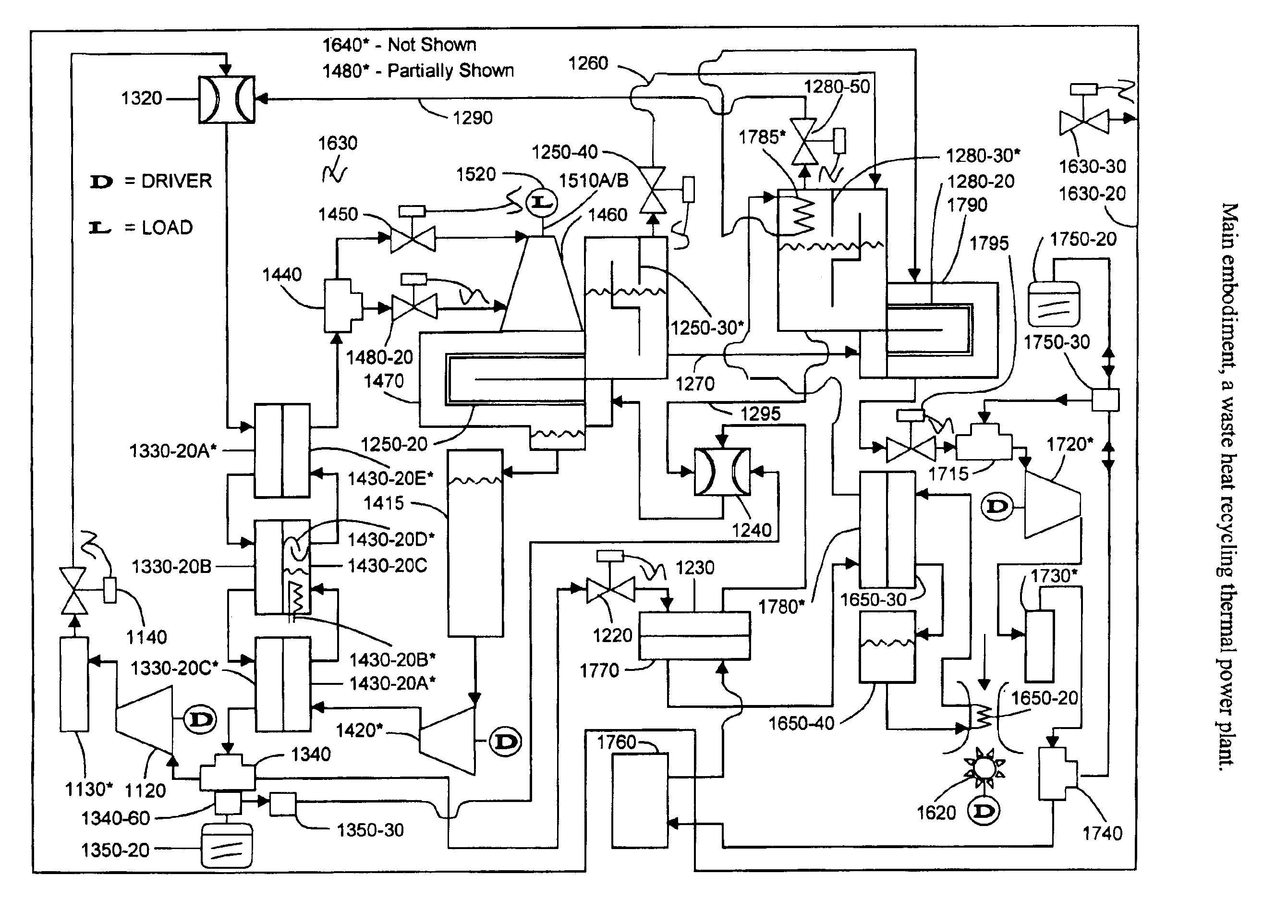
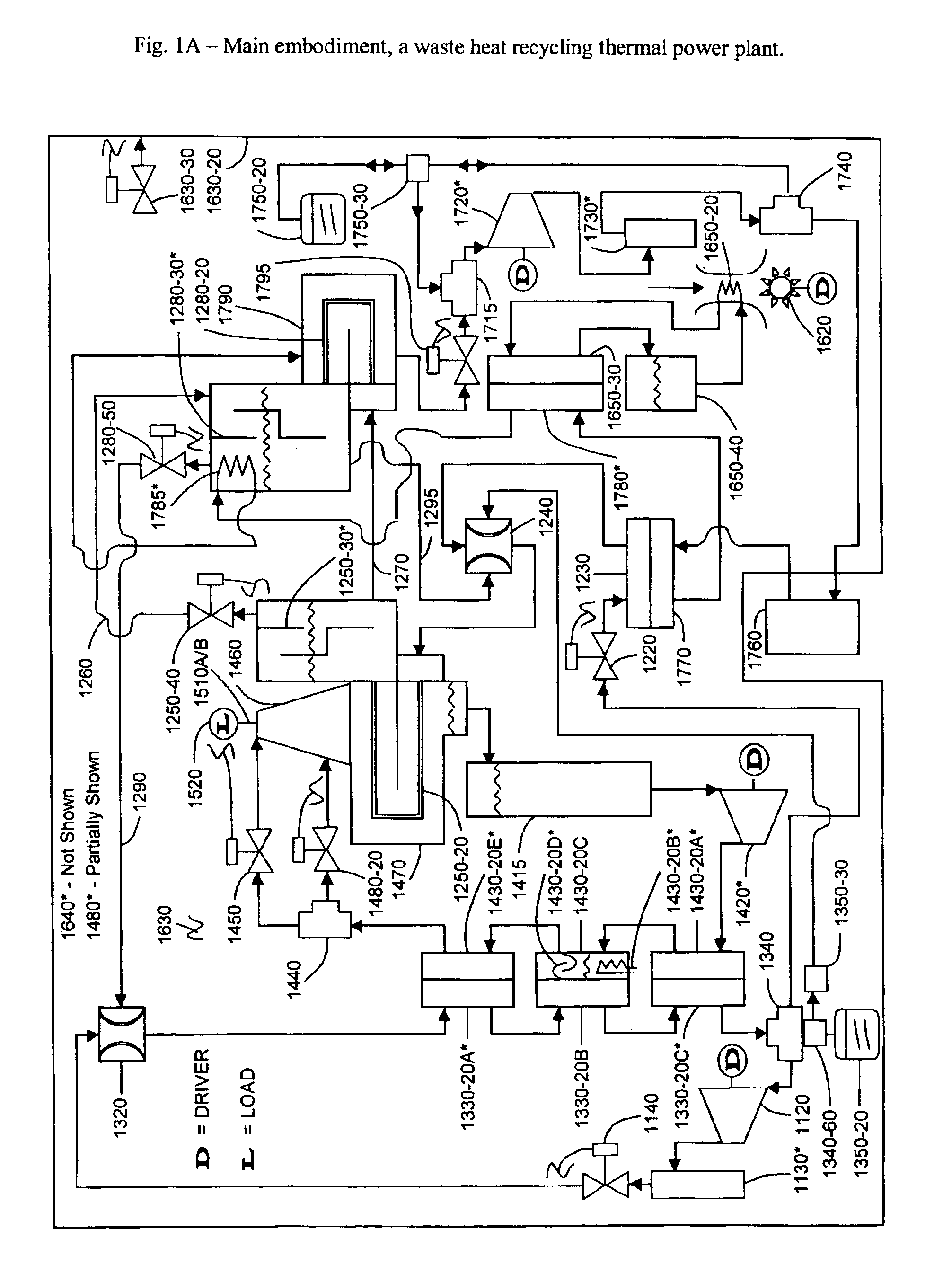
[0039]A waste heat recycling thermal power plant 1000 (FIG. 1A) consists primarily of two conjoined circuits, a motive flow circuit 1100 and a suction flow circuit 1200 of a volatile working fluid (the conjoined portions of motive flow circuit 1100 and suction flow circuit 1200 are identified as a conjoined flow circuit 1300). Additionally, waste heat recycling thermal power plant 1000 includes an incorporated heat engine flow circuit 1400 connected to a mechanical output device 1500, a heat recovery flow circuit 1600 (optional, a heat source flow circuit 1700, and the subcomponents contained therein. These circuits and their subcomponents are described below; the interconnecting piping / ducting is described only where necessary to add clarity to the description.

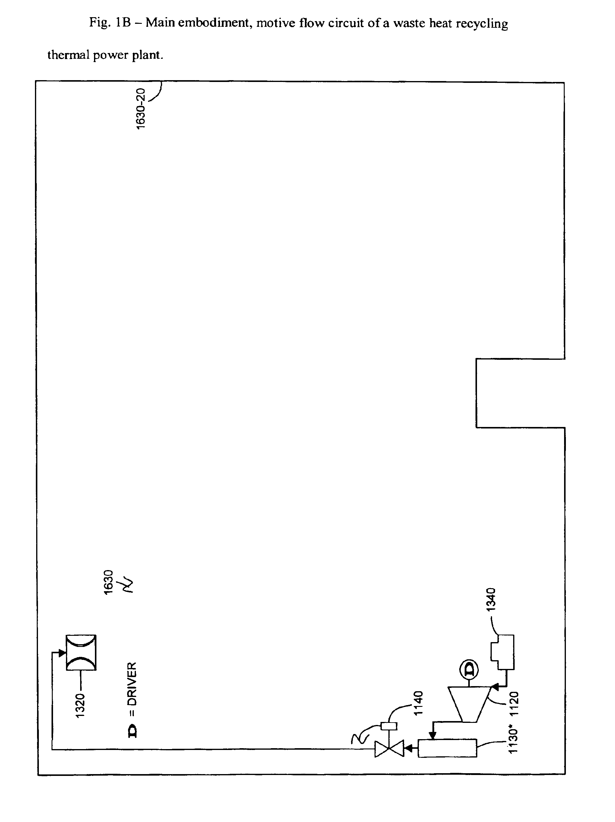
[0040]Motive flow circuit 1100 (FIG. 1B) which originates at a cfd flow separation chamber 1340-30, and successively flows through: a cfd motive flow discharge 1340-40, an mfc fluid transfer ...


PUM


Abstract

This invention, a waste heat recycling thermal power plant (1000), extracts heat from the environment, and concentrates this heat to produce a cfc super-ambient temperature heat source (1330) having an elevated temperature sufficient to supply a useable heat flow to an incorporated heat engine (e.g., Rankine cycle, Stirling cycle, Seebeck cycle, etc.) flow circuit (1400). Further, waste heat recycling thermal power plant (1000) produces an sfc sub-ambient temperature heat sink (1250), thus increasing the applied temperature differential, thereby permitting the thermal efficiency of ihefc pressure expansion device (1460) to be increased as well. Lastly, waste heat recycling thermal power plant (1000) captures for reuse, much of the waste heat that its own operation liberates, thus lowering its net energy utilization per unit of mechanical power produced (a.k.a., heat rate, Btu / kwhr). In the main embodiment of its use, waste heat recycling thermal power plant (1000) would be used as the driver for a mod driven mechanical device (1520), specifically an electrical generator. Deriving its source heat by intercepting the heat that would be rejected to the environment by an electrical power generating station's cooling device, and routing this heat to waste heat recycling thermal power plant (1000). Then converting this heat to mechanical power, and subsequently to electrical power. This would result in an improvement of the electrical power generating station's net electrical power generating capacity and fuel efficiency, while simultaneously reducing the quantity of thermal (and potentially chemical) pollution released to the environment.

Description

BACKGROUND OF THE INVENTION[0001]1. Field of the Invention[0002]This invention relates to the field of thermal power plants, specifically of the type that recycle a significant portion of the heat that is normally rejected to the environment by “conventional” thermal power plants.[0003]2. Description of the Prior Art[0004]A search of the prior art reveals numerous inventions that attempt to improve the efficiency of various types (e.g., Rankine cycle, Stirling cycle, Brayton cycle, Otto cycle, Diesel cycle, Seebeck cycle, etc.) of heat engines and the thermal power plants in which they are contained.[0005]In 1824, Nicolas Leonard “Sadi” Carnot, a French engineer and founder of the discipline now known as “Thermodynamics,” published his treatise (Reflexions sur la puissance motrice du feu et sur les machines propres a developper cette puissance) on the nature of heat engines. The relevant finding of this paper was that all heat engines, in order to function, first receive heat from a...

Claims


Application Information

Patent Timeline
Patent Type & Authority Patents(United States)
IPC IPC(8): F01K1/00F01K7/34F01K7/00F01K21/00
CPCF01K21/00
Inventor KIRBY, TIMOTHY MICHAELKIRBY, WANDA MARIE
Owner KIRBY TIMOTHY MICHAEL
Why Eureka
Try Eureka