Cross member for vehicle bumper bar and method for making same

a cross member and bumper bar technology, applied in the direction of roofs, printing, instruments, etc., can solve the problems of difficult manufacturing of bumper beams or bars out of some high strength steel, inability to meet the requirements of high strength steel, etc., to achieve the effect of less cos

Inactive Publication Date: 2005-09-27
ZOHAR TT ACQUISITION LLC
View PDF21 Cites 42 Cited by
  • Summary
  • Abstract
  • Description
  • Claims
  • Application Information

AI Technical Summary

Benefits of technology

[0012]The present invention provides a vehicle bumper bar and method of making the bumper bar from high strength or ultra-high strength steel and roll formed into a tubular cross section of B shape. The cross member may be made from a variety of steels of varying thickness, cut to different lengths and bent to different curvatures for various automobiles. The equipment utilized in the system remain the same since the cross section remains the same for different length and different curvature bumpers. This system thus provides an economical advantage over the prior art methods and equipment discussed previously where the steel is fabricated in tubular form and swept in one apparatus since there will be no additional tooling costs for providing bumpers of various lengths.
[0013]With the present invention, the method and equipment employed may be used to make bumpers or cross members of different lengths and curvatures without changing the roll formers since the same cross section is utilized. Thus, a less costly tooling system is provided for making various bumpers for different manufacturers which is extremely important because of the competitiveness of the industry.

Problems solved by technology

It has been difficult to manufacture the bumper beam or bar out of some high strength steel because such bar requires a curvature to be placed therein.
In the past, when high strength steel is roll formed into the desired sweep or curvature, the material of the cross members has been damaged during the process resulting in unacceptable quality.
Formability of high strength steel is difficult than with low carbon steels because of greater spring-back and reduced ductility.
A disadvantage of the methods and apparatuses disclosed in the Sturrus and Sturrus et al patents is that the method and apparatus for forming the straight tubular “B” section cross member and the equipment for forming the sweep in the cross members are connected together in one line, with the severing of the cross member from the roll formed member being located down stream of the welding station.

Method used


Image

  • Cross member for vehicle bumper bar and method for making same
  • Cross member for vehicle bumper bar and method for making same
  • Cross member for vehicle bumper bar and method for making same

Examples


Embodiment Construction

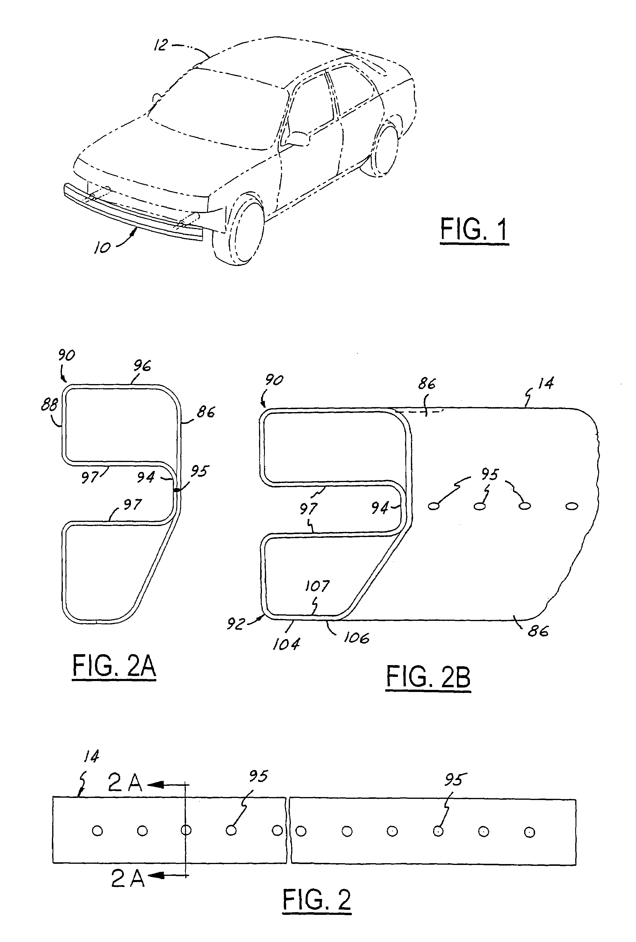
[0023]The bumper 10 of the present invention is illustrated in FIG. 1 mounted on the front of an automobile 12 although it should be understood that the bumper, with or without a sweep, may be mounted either on the front or rear of the automobile 12.

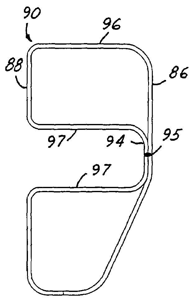
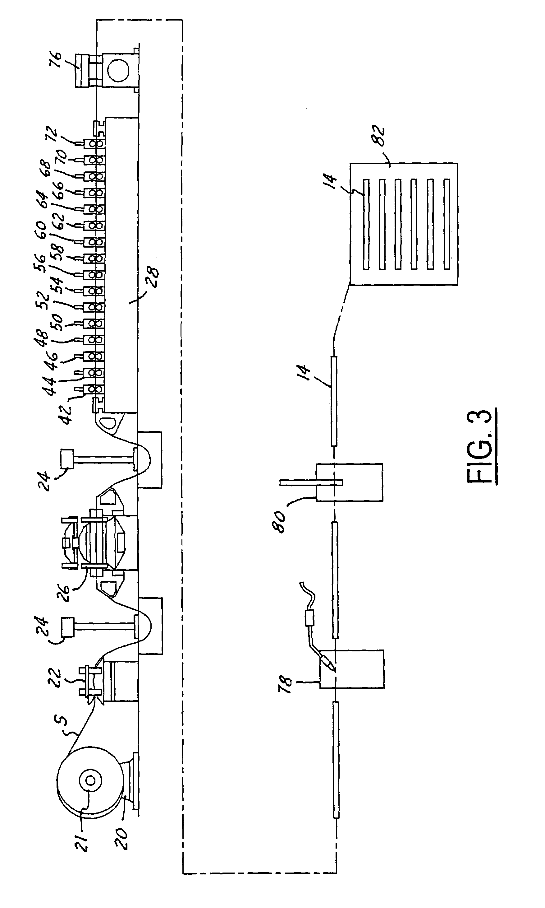
[0024]The bumper beam 10 is made in two manufacturing stages. The first manufacturing stage is illustrated in FIG. 3 where the method and apparatus is demonstrated and illustrated for making a straight tubular cross member 14 as illustrated in FIG. 2 with a B shaped cross section as shown in FIG. 2A. The equipment and method utilized for manufacturing the straight tubular cross member 14 includes an in-line system of standard metal forming and welding equipment including a steel roll holder 20 rotatably supporting a steel roll 21 of strip steel S; a straightener system or straightener 22 and a pair of guide posts 24 located on opposite sides of a punch press 26 for directing steel strip as it moves along the line. Downstream from the pun...


PUM

PropertyMeasurementUnit
lengthaaaaaaaaaa
tensile strengthaaaaaaaaaa
frequencyaaaaaaaaaa

Abstract

A two step system or stage is provided to manufacturer a bumper of “B” shape cross section including a roll forming-welding stage where a straight cross member of a length to mount on the front or rear of various models of automobiles and the bending stage where any curvature or sweep is introduced into the cross member as required by the design of the automobile. The roll forming welding stage include the spot or tack welding of the front wall to the web followed immediately by welding together without any gaps therebetween the abutting longitudinal edges utilizing a high frequency welder. Thus, the “B” shaped cross section of the bumper may be used to make different bumpers of various lengths and curvatures.

Description

CROSS REFERENCE TO RELATED APPLICATION[0001]This application claims the benefit of U.S. Provisional Patent Application Ser. No. 60 / 539,511 filed Jan. 26, 2004.FIELD OF THE INVENTION[0002]This invention relates to a roll formed tubular vehicle cross member, bumper beam or bar fabricated from high or ultra-high strength steel. The cross member may be either straight or provided with a sweep or curvature having a value of more than 10. The resulting tubular bumper has a high impact resistance, low weight and relatively low cost of manufacture.BACKGROUND OF THE INVENTION[0003]Bumper beams or cross members for vehicles, particularly automobiles, are made from high strength or ultra-high strength steel. It has been difficult to manufacture the bumper beam or bar out of some high strength steel because such bar requires a curvature to be placed therein. It is necessary to roll form the cross member to obtain the desired curvature. In the past, when high strength steel is roll formed into t...

Claims


Application Information

Patent Timeline
Patent Type & Authority Patents(United States)
IPC IPC(8): B60R19/02G03B27/54B21D5/08B21D53/88B60R19/18
CPCB21D5/086B21D53/88B60R19/18B60R2019/1826
Inventor GRABER, DONALD G.
Owner ZOHAR TT ACQUISITION LLC
Why Eureka
Try Eureka