Track pin bushing having a metallurgically bonded coating

a technology of metallurgically bonded coating which is applied in the direction of ring springs, vehicle cleaning, hoisting equipment, etc., can solve the problems of accelerated wear of track components such as track pins and track pin bushings, and the bushings of track pins in endless tracks of track-type machines are subject to very severe operating environments

Inactive Publication Date: 2005-09-27
DEERE & CO
View PDF37 Cites 43 Cited by
  • Summary
  • Abstract
  • Description
  • Claims
  • Application Information

AI Technical Summary

Problems solved by technology

The track pin bushings in endless tracks of a track-type machine are subjected to very severe operating environments.
A track that is adjusted too tight can increase friction and cause accelerated wear to track components such as track pins and track pin bushings.
In an extreme case, severely tight track adjustment can cause the track to run extremely hot and “draw-back” the hardness of track pins and track pin bushings, i.e., heat treat the components resulting in a reduction in the components' hardness, and even cause the track pins and track pin bushings to fuse together.
At the other end of the spectrum, a too loose track can allow drive sprocket teeth to jump links, especially in reverse, causing wear to the teeth and the track pin bushings.
There are two types of wear on track pins and track pin bushings-external wear and internal wear.
Additionally, where the track pin bushings are fitted into the track link counterbores, internal wear can occur on the outside diameter of the ends of the track pin bushings.
Thus, current track pins and track pin bushings in endless tracks experience wear and stress which can negatively impact the service life of the track pin bushing.
However, these materials and methods still result in a relatively short service life.
However, the track pins and track pin bushings must be turned prior to being worn past the wear limit, or they will not be serviceable.
Thus, frequent inspection and maintenance of track pins and track pin bushings occurs to identify and ameliorate components that have worn, resulting in the associated down time of equipment and personnel.
However, one problem with this method of hardfacing is forming a metallurgical bond between the metal surface and the hardfacing material, particularly when other portions, i.e, the uncoated portions, of the metal surface are to be subsequently treated to obtain a wear-resistant character, i.e., through a heat treatment process that occurs after the hardfacing.
However, wear-resistant coatings applied to carburized or case-hardened surfaces do not readily metallurgically bond to the surface.
Further, application of the wear-resistant coating prior to carburizing results in oxidation of the wear-resistant coating during subsequent heat treatments with an adverse impact on the wear-resistant properties of the coating.

Method used


Image

  • Track pin bushing having a metallurgically bonded coating
  • Track pin bushing having a metallurgically bonded coating
  • Track pin bushing having a metallurgically bonded coating

Examples


Embodiment Construction

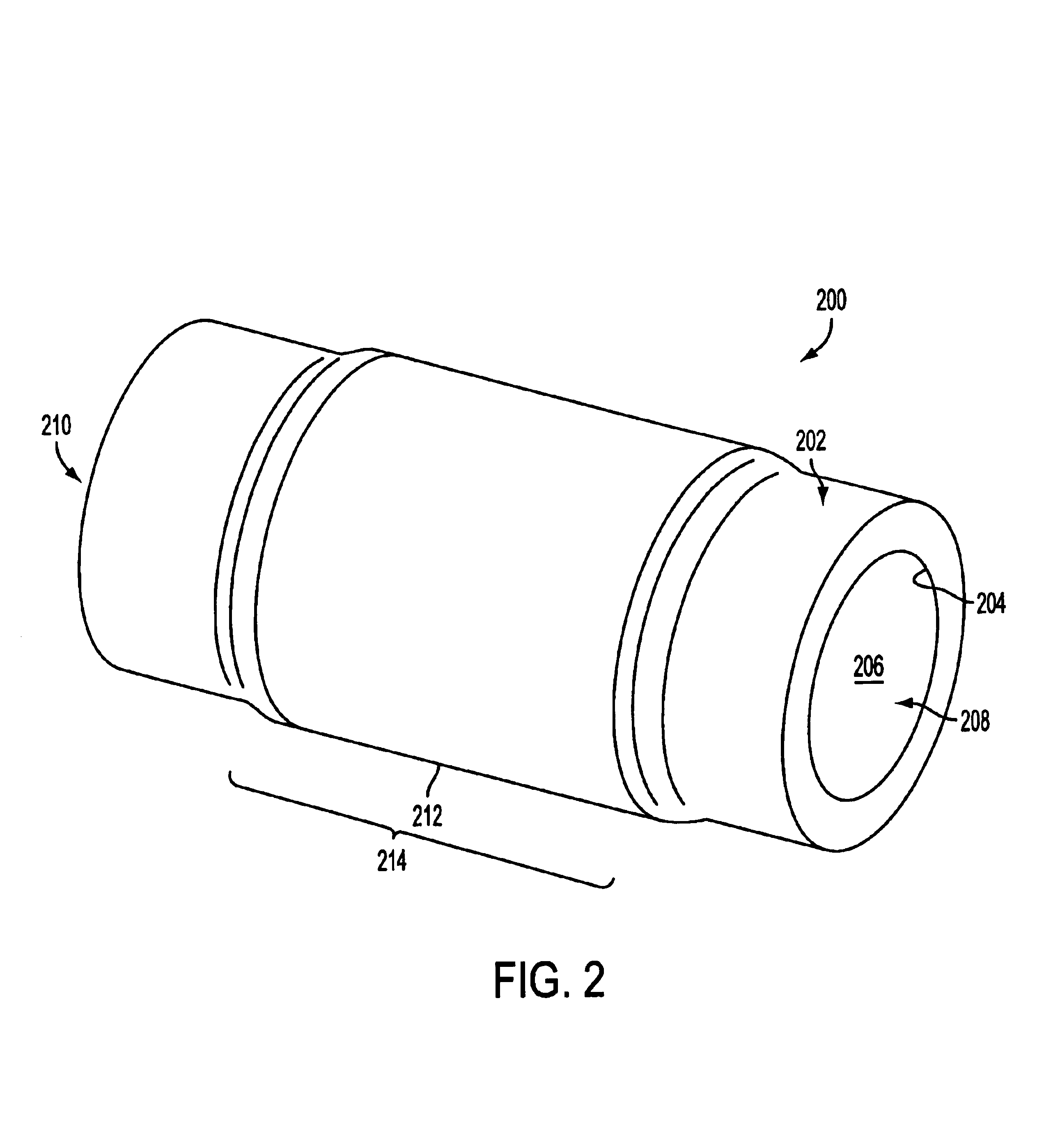
[0047]A track pin bushing cooperates with a track pin in an endless track of a track-type machine, such as a crawler tractor. In an exemplary embodiment and as shown in FIG. 2, the track pin bushing 200 has a tubular body formed of an iron-based alloy, at least a section of which is case hardened, i.e., the outer surface, the inner surface, the ends, or portions or combinations thereof have been carburized and quenched. The track pin bushing 200 has an outer surface 202 having an outer diameter and an inner surface 204 having an inner diameter. The inner diameter defines the circumference of an axial bore 206 extending from the first end 208 to the second end 210 of the track pin bushing 200. A wear-resistant coating 212 is disposed on and metallurgically bonded to a portion 214 of the track pin bushing 200 that has been exposed by the removal of at least a portion of the case hardened section to a depth sufficient to expose a non-carburized layer of the iron-based alloy.

[0048]In an...


PUM

PropertyMeasurementUnit
Vickers hardnessaaaaaaaaaa
thicknessaaaaaaaaaa
depthaaaaaaaaaa

Abstract

A track pin bushing for cooperating with a track pin in an endless track has a tubular body with a metallurgically bonded wear-resistant coating and a method for forming such a coated track pin bushing is taught herein. The tubular body, formed of an iron-based alloy, has an outer surface that is carburized and quenched, i.e., case-hardened, in at least a section thereof. At least a portion of the case hardened section has been removed to a depth sufficient to expose a non-carburized layer of the iron-based alloy. A hard metal alloy slurry is disposed on the non-carburized layer and forms a metallurgical bond between the non-carburized layer and the coated unfused slurry by fusing the hard metal alloy. The thickness of the unfused slurry is adjusted to be from 1.67 to 2.0 times a final thickness of the wear-resistant coating. The wear-resistant coating comprises a fused, metal alloy comprising at least 60% iron, cobalt, nickel, or alloys thereof. The portion of the outer surface with the wear-resistant coating corresponds to a contact surface adapted to engage with a drive sprocket in the endless track of the track-type vehicle.

Description

FIELD OF THE INVENTION[0001]The present invention relates generally to track pin bushings for endless tracks of track-type machines. In particular, it relates to track pin bushings having a wear resistant coating that is metallurgically bonded to an outside diameter surface of the track pin bushing where a drive sprocket engages and disengages the surface.STATE OF THE ART[0002]In the discussion of the state of the art that follows, reference is made to certain structures and / or methods. However, the following references should not be construed as an admission that these structures and / or methods constitute prior art. Applicant expressly reserves the right to demonstrate that such structures and / or methods do not qualify as prior art against the present invention[0003]An endless track is a chain made up of links, track pin bushings, track pins, and shoes. FIG. 1 shows these components in a representative section of a track on a track-type machine, i.e., a crawler tractor. Each sectio...

Claims


Application Information

Patent Timeline
Patent Type & Authority Patents(United States)
IPC IPC(8): B62D55/20B62D55/21
CPCB62D55/21Y10T29/49707
Inventor WODRICH, TIMOTHY D.NIEMANN, TODD B.REVANKAR, GOPAL S.
Owner DEERE & CO
Why Eureka
Try Eureka