
Methods and apparatus for controlling operation of a microwave oven in a network

a microwave oven and network technology, applied in the field of microwave oven systems, can solve problems such as unpractical examples, and achieve the effect of improving the manner of use, varying or improving the di

Inactive Publication Date: 2005-09-27
SHARP KK
View PDF30 Cites 82 Cited by
  • Summary
  • Abstract
  • Description
  • Claims
  • Application Information

AI Technical Summary

Benefits of technology

[0009]By the microwave oven system, it becomes possible for the user to directly supply the heating and control data corresponding to a desired cooking recipe provided by the home page through the Internet to the microwave oven to be recognized, simply by operating the transfer instruction button output on the home page screen. In other words, it becomes possible to omit the process of decoding the heating control data to be recognizable by the microwave oven, thus speedy control of the heating operation is possible. Therefore, the system is very practical as the desired cooking recipe can be automatically heated and cooked quickly by the microwave oven.
[0146]Communication between the above described information processing apparatus and the microwave oven becomes possible when the apparatus side connector unit is inserted to the microwave oven side connector unit. Therefore, there is no limit in the arrangement of the microwave oven and the information processing apparatus, and therefore degree of freedom in arranging the microwave oven and the information processing apparatus is improved. Further, wiring for communication is not necessary between the microwave oven and the information processing apparatus, which is convenient for the user.

Problems solved by technology

The example, however, is not very practical, as specific procedure of how to obtain the cooking information desired by the user from a home page, how to supply the information to a microwave oven as the electrical appliance and how the process for heating and cooking takes place in the microwave oven are not at all described.

Method used


Image

  • Methods and apparatus for controlling operation of a microwave oven in a network
  • Methods and apparatus for controlling operation of a microwave oven in a network
  • Methods and apparatus for controlling operation of a microwave oven in a network

Examples


first embodiment

[0261

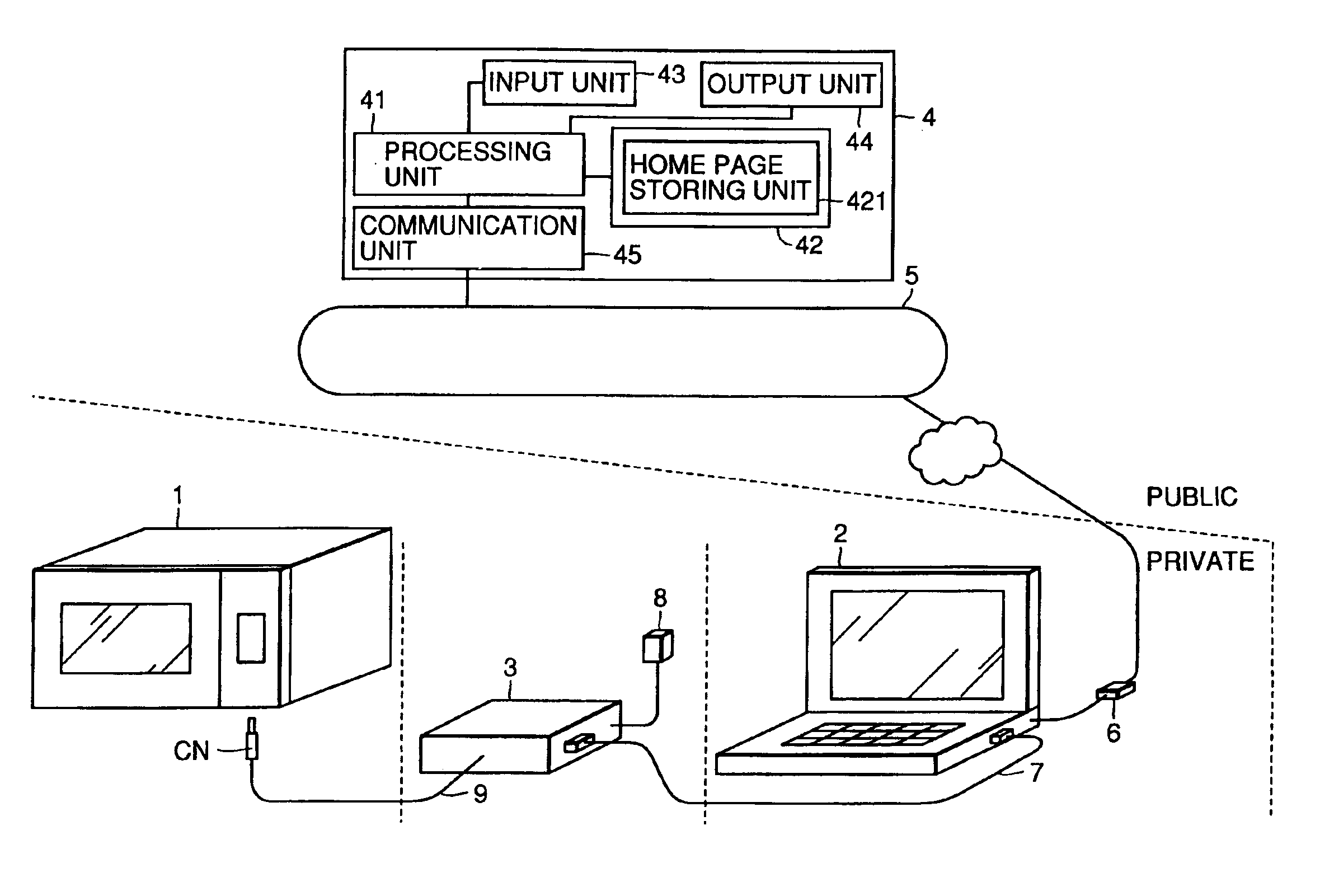
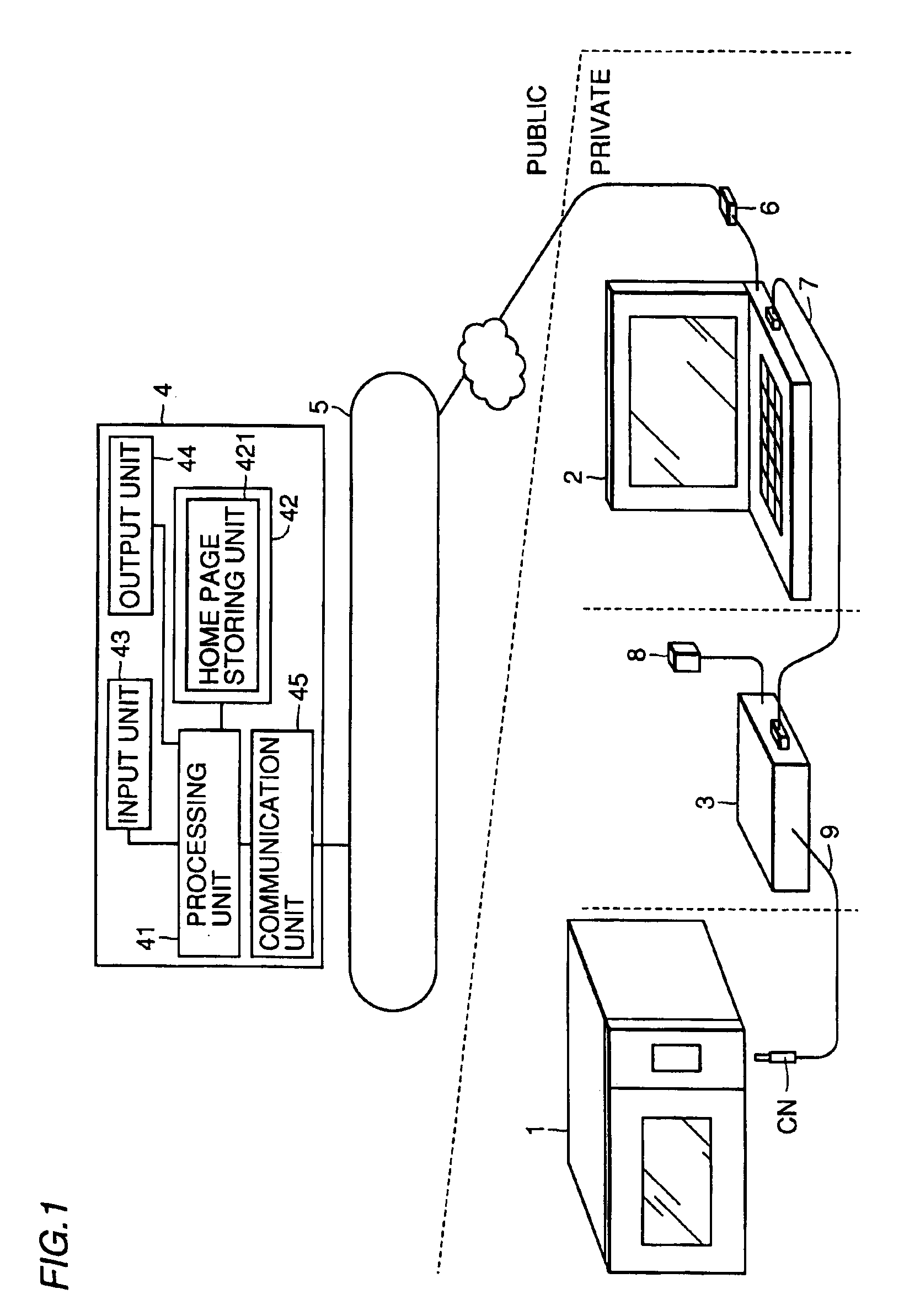
[0262]FIG. 1 is a schematic diagram showing a configuration of the microwave oven system in accordance with the first embodiment of the present invention.

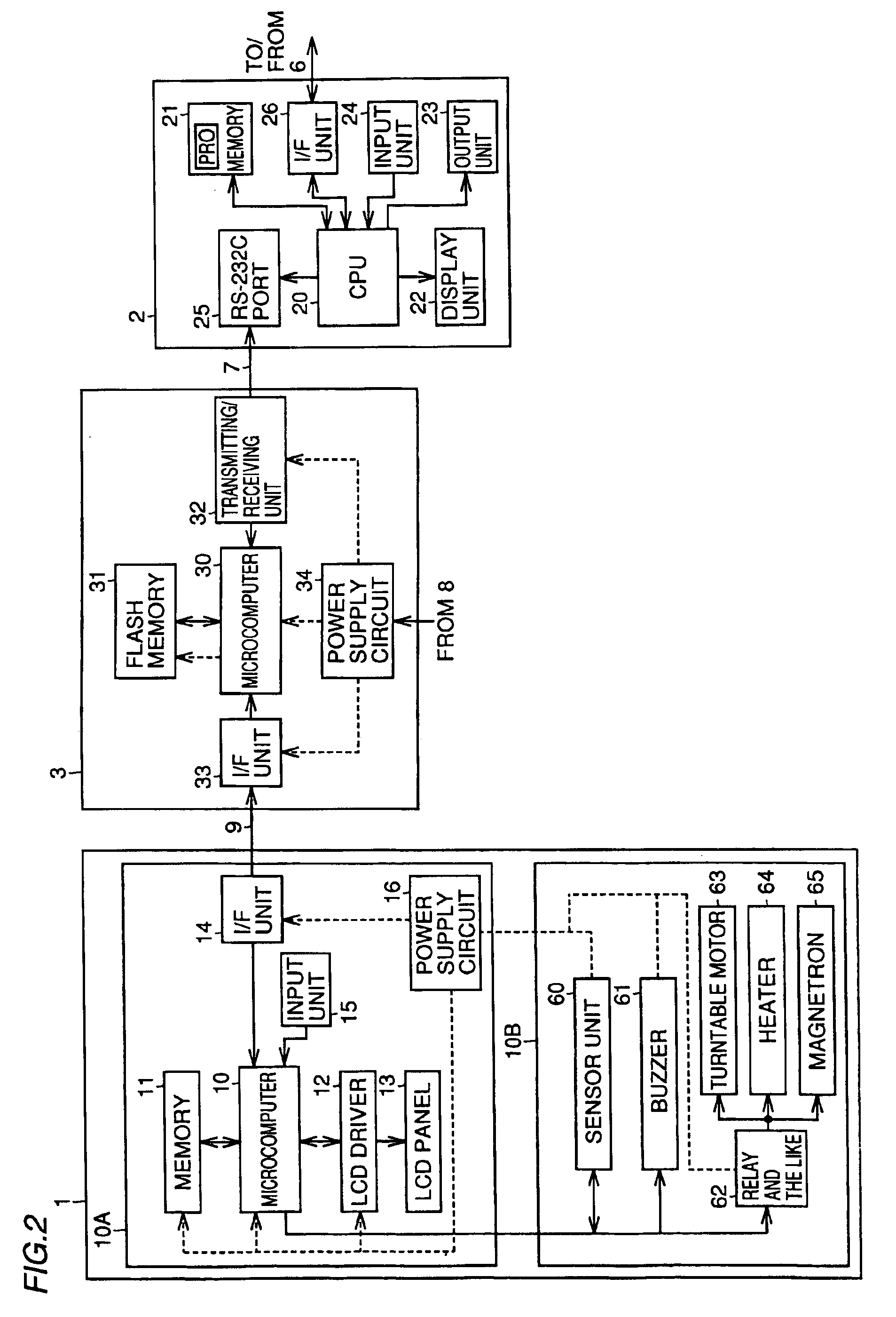
[0263]FIG. 2 is a block diagram showing configurations of respective units of FIG. 1.

[0264]Referring to FIG. 1, the microwave oven system includes, in public, the Internet 5 and a host computer 4 connected thereto, and in private, a microwave oven 1, a personal computer 2 connected through a modem 6 to the Internet 5, and a relay box 3 fed from an AC adapter 8, as a relay apparatus for connecting personal computer 2 and microwave oven 1, converting and communicating signals therebetween. In private, microwave oven 1 and relay box 3 are connected by a three-line cable 9. For this connection, a connector CN at one end of the three-line cable 9 is connected to an input / output terminal, not shown, of microwave oven 1. In private, personal computer 2 and relay box 3 are connected by an RS-232C cable 7 for communication in accordanc...

second embodiment

[0334

[0335]Second embodiment will be described in the following. FIG. 22 is a schematic diagram representing a configuration of a microwave oven system in accordance with the second embodiment of the present invention. FIG. 23 is a block diagram showing configurations of microwave oven 1A and personal computer 2A. In FIG. 22, microwave oven 1A and personal computer 2A have infrared emitting / receiving units 66 and 27 for wireless communication by IRDA (Infrared Data Association) therebetween. When microwave oven 1A and personal computer 2A of FIG. 23 are compared with microwave oven 1 and personal computer 2 of FIG. 2, respectively, there are the following differences. Namely, microwave oven 1A is provided with an IrDAI / F unit 141 related to the infrared emitting / receiving unit 66 in place of I / F unit 14 of FIG. 2, and personal computer 2A is provided with an IrDAI / F unit 251 related to an infrared emitting / receiving unit 27 in place of RS-232C port 25 of FIG. 2. Other structures of ...

third embodiment

[0337

[0338]A third embodiment will be described in the following. FIG. 24 is a schematic diagram representing the microwave oven system in accordance with the third embodiment of the present invention. FIG. 25 represents block configurations of microwave oven 1B and personal computer 2B of FIG. 24.

[0339]In FIG. 24, microwave oven 1B and personal computer 2B are provided with RAM card inlets 67 and 28, which are card slot interfaces to which an RAM card 80 is inserted, for transferring data therebetween by using a card shaped RAM (Random Access Memory) card 80.

[0340]When microwave oven 1B and personal computer 2B are compared with microwave oven 1 and personal computer 2 of FIG. 2, there are the following differences. More specifically, microwave oven 1B is provided with an RAM card I / F unit 142 for accessing the data of RAM card 80 inserted through RAM card inlet 67, in place of I / F unit 14 of FIG. 2, and that personal computer 2B is provided with an RAM card I / F unit 252 for access...


PUM


Abstract

A microwave oven, a relay box communicating with the microwave oven and a personal computer communicating with the relay box are provided in private. The personal computer is connected to a host computer storing home page information, through the public Internet. A home page storing unit of the host computer stores, corresponding to each of a plurality of cooking recipes, recipe data directly recognized by microwave oven including heating control data for heating and cooking the cooking recipe by the microwave oven, a button to be operated for transferring the recipe data through the Internet to personal computer and image display data for displaying information related to the cooking recipe as a home page image display. Therefore, in accordance with the heating control data downloaded and supplied to personal computer, microwave oven is controlled to heat and cook the desired cooking recipe.

Description

BACKGROUND OF THE INVENTION[0001]1. Field of the Invention[0002]The present invention relates to a microwave oven system allowing control of a microwave oven of each home in accordance with the information supplied from the side of a host computer through a communication network, a microwave oven, a relay apparatus, an information processing apparatus, a host computer and a computer readable recording medium recording home page information. More specifically, the present invention relates to a microwave oven system accessing a host computer having prescribed home page information through the Internet, allowing control of the microwave oven based on the information from the host computer, a microwave oven, a relay apparatus, an information processing apparatus, a host computer and a computer readable recording medium recording home page information.[0003]2. Description of the Background Art[0004]Japanese Patent Laying-Open No. 10-276478 discloses an apparatus controlling household ap...

Claims


Application Information

Patent Timeline
Patent Type & Authority Patents(United States)
IPC IPC(8): H05B6/68
CPCH05B6/688
Inventor ISHIKAWA, KAZUHIKOFUJIKAWA, TOORUOTA, TOMOKO
Owner SHARP KK
Learn More