[0011]It is, therefore, an object of the present invention to provide a small apparatus for holding a stable condition at two positions which has a self-holding function and can achieve the positive reversible movement between two positions. It is another object of the present invention to provide an apparatus for holding a stable condition at two positions which can set the movable
stroke of the working member at about 0.1 mm˜0.5 mm. It is another object of the present invention to provide an apparatus for holding a stable condition at two positions which has a simple structure and can achieve positive positioning at two positions. It is other object of the present invention to provide a lens apparatus using an apparatus for holding a stable condition at two positions which has a self-holding function and a very small
hysteresis in its operation. It is a further object of the present invention to provide a lens apparatus using an apparatus for holding a stable condition at two positions which can set the movable stroke of the working member at about 0.1 mm˜0.5 mm. It is a further object of the present invention to provide a lens apparatus using an apparatus for holding a stable condition at two positions which has a simple structure and can achieve positive positioning at two positions.
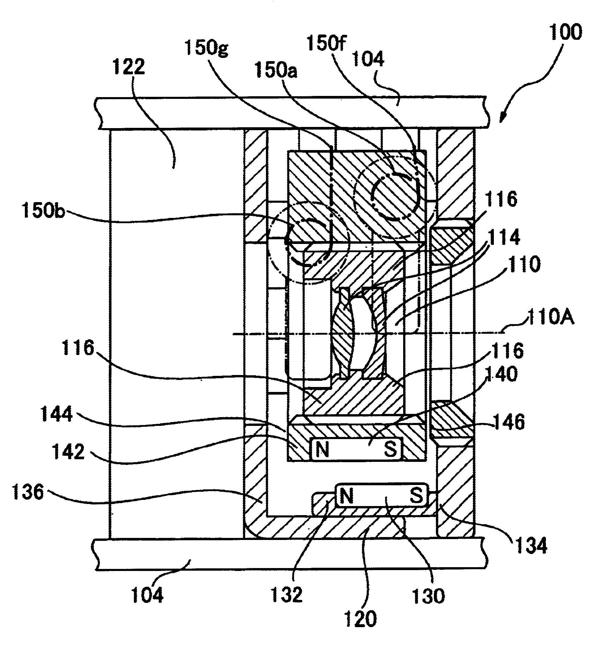
[0012]According to the present invention, there is provided an apparatus for holding a stable condition at two positions comprising a driving magnet having driving magnetic poles and adapted to be movable in two directions; a driven magnet having driven magnetic poles arranged to be always repulsed by the driving magnetic poles and adapted to be movable in two directions; a motion limiting means for limiting the movement of the driven magnet; and a driving means for driving the driving magnet in two directions. In the apparatus for holding a stable condition at two positions of the present invention, it is so constructed that a direction of the repulsion force applied to the driven magnet by the driving magnet is changed, at a stage during which the driving magnet is moved to a first moving direction by the driving means, to a second acting direction of repulsion force opposite to a first acting direction of repulsion force which has been caused until said stage. Further in the apparatus for holding a stable condition at two positions of the present invention, it is so constructed that a direction of the repulsion force applied to the driven magnet by the driving magnet is changed, at a stage during which the driving magnet is moved to the second moving direction opposite to the first moving direction by the driving means, to the first acting direction of repulsion force opposite to the second acting direction of repulsion force which has been caused until said stage. It is preferable that the driving means may be made of shape-memory
alloy and may include a driving element for driving the driving magnet. This structure enables to realize a small apparatus for holding a stable condition at two positions which has a simple structure and can achieve positive positioning at two positions.
[0014]It is also preferable that the driving means may comprise a driving element made of shape-memory
alloy, the driving element may include a first driving element portion for driving the driving magnet toward the first moving direction and a second driving element portion for driving the driving magnet toward the second moving direction, the driving means may further comprise a first wiring for supplying a current to the first driving element portion, a second wiring for supplying a current to the second driving element portion, and a power supplying portion for selectively supplying the current to the first wiring or the second wiring. This structure enables to realize a simple apparatus for holding a stable condition at two positions without using any means such as a connecting mechanism, an elastic member or a
cam.
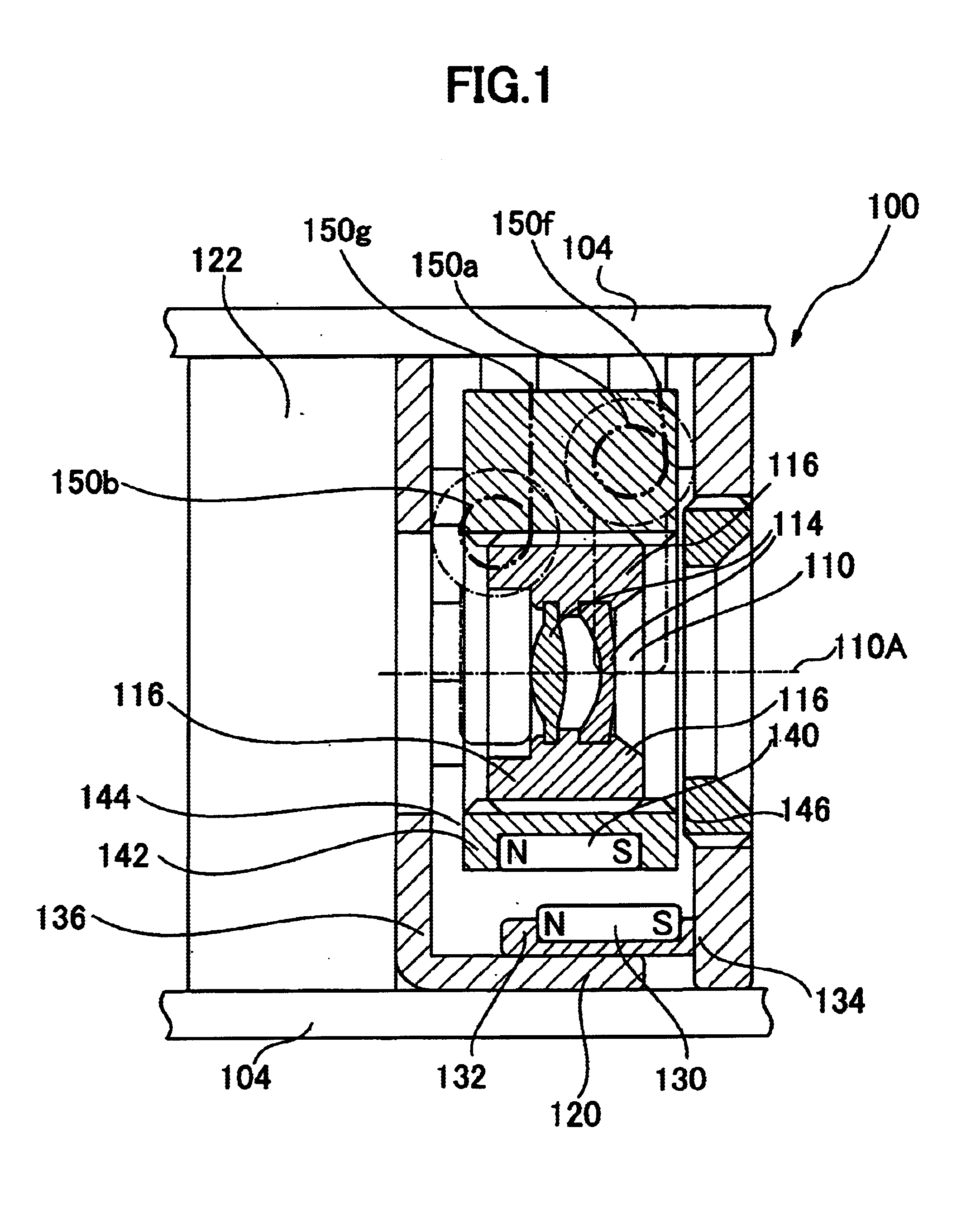
[0015]Further according to the present invention, there is provided lens apparatus having a lens
system including a moving lens comprises a lens supporting member, and an apparatus for holding a stable condition at two positions mentioned above. This lens apparatus is characterized in that the moving lens can be driven by the movement of a driven magnet of the apparatus for holding a stable condition at two positions. This structure enables to realize a
small lens apparatus having a simple structure and moving lens of positive operation.
[0016]As described above, the apparatus for holding a stable condition at two positions comprises a driving magnet, a driven magnet arranged to be always repulsed by the driving magnetic poles and adapted to be movable in two directions, a driving means (i.e. an
actuator) for driving the driving magnet in two directions, and the driving means (actuator) is a driving element made of shape-memory
alloy. Thus the apparatus for holding a stable condition at two positions of the present invention has following superior effects: Since the apparatus of the present invention does not require any means such as a connecting mechanism, an elastic member or a
cam, it is possible to drive the apparatus from the outside of the housing such as a camera cone and thus to make the structure of the apparatus simple; Since the apparatus of the present invention comprises the driving magnet and the follower magnet, the actuating force acting on the follower magnet during the way of its going to the stable position becomes maximum at a point beyond the neutral point. Accordingly, the
hysteresis of magnet during operation is very small and thus it is possible to positively position the follower magnet at two positions; According to the apparatus of the present invention, it is possible to make the movable stroke of the working member driven by the follower magnet a small amount as 0.1 mm˜0.5 mm and thus to make the apparatus small; According to the lens apparatus of the present invention using the apparatus for holding a stable condition at two positions of the present invention, it has the self-holding function, the
hysteresis of magnet during the operation of the apparatus for holding a stable condition at two positions is very small, and the movable stroke of the working member small as 0.1 mm˜0.5 mm; and Since the apparatus for holding a stable condition at two positions is simple in structure, the lens apparatus using it can be also compacted.

