
Apparatus for receiving moving pictures

a technology for moving pictures and apparatuses, applied in the field of apparatuses for receiving moving pictures, can solve the problems of difficult relation between high definition and compression ration, difficulty in providing mpeg-2 mp@hl of high image quality of color components and high textured images, and insufficient processing of video data for mpeg-2 mp@hl, etc., to achieve the effect of reducing the external memory of a video decoder, high distinction, and fast processing speed

Inactive Publication Date: 2005-09-27
LG ELECTRONICS INC
View PDF8 Cites 31 Cited by
  • Summary
  • Abstract
  • Description
  • Claims
  • Application Information

AI Technical Summary

Benefits of technology

[0028]The object of the present invention is to provide an apparatus for receiving moving pictures enabling to reduce an external memory of a video decoder for MPEG-2.
[0029]Another object of the present invention is to provide an apparatus for receiving moving pictures enabling to maintain high distinction as well as fast processing speed.
[0030]A further object of the present invention is to provide an apparatus for receiving moving pictures enabling to maintain high definition image by predicting the current pixels.

Problems solved by technology

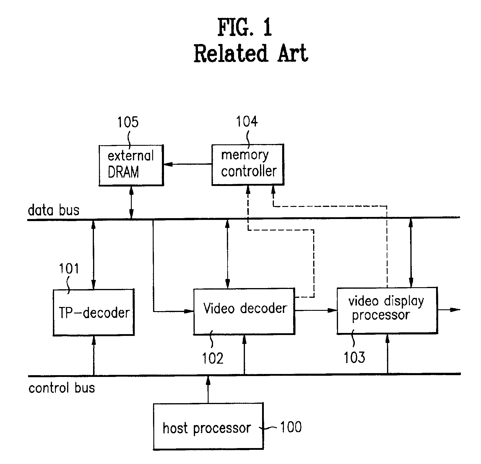
Unfortunately, the external memory 105 in FIG. 1 is proper for processing small data but fails to be proper for processing video data for MPEG-2 MP@HL.
However, the above-proposed methods with 50% to 75% compression ratio have difficulty in providing MPEG-2 MP@HL of high image quality of color components and high textured images.
Namely, high definition is inverse proportional to a compression ratio and the relation between the high definition and compression ration needs very complicated algorithm.
Unfortunately, when a memory reduction circuit is embodied as an integrated circuit (IC), it is difficult to implementing the complicated algorithms as well as the number of gates is increased.

Method used


Image

  • Apparatus for receiving moving pictures
  • Apparatus for receiving moving pictures
  • Apparatus for receiving moving pictures

Examples


Embodiment Construction

[0053]Reference will now be made in detail to the preferred embodiments of the present invention, examples of which are illustrated in the accompanying drawings.

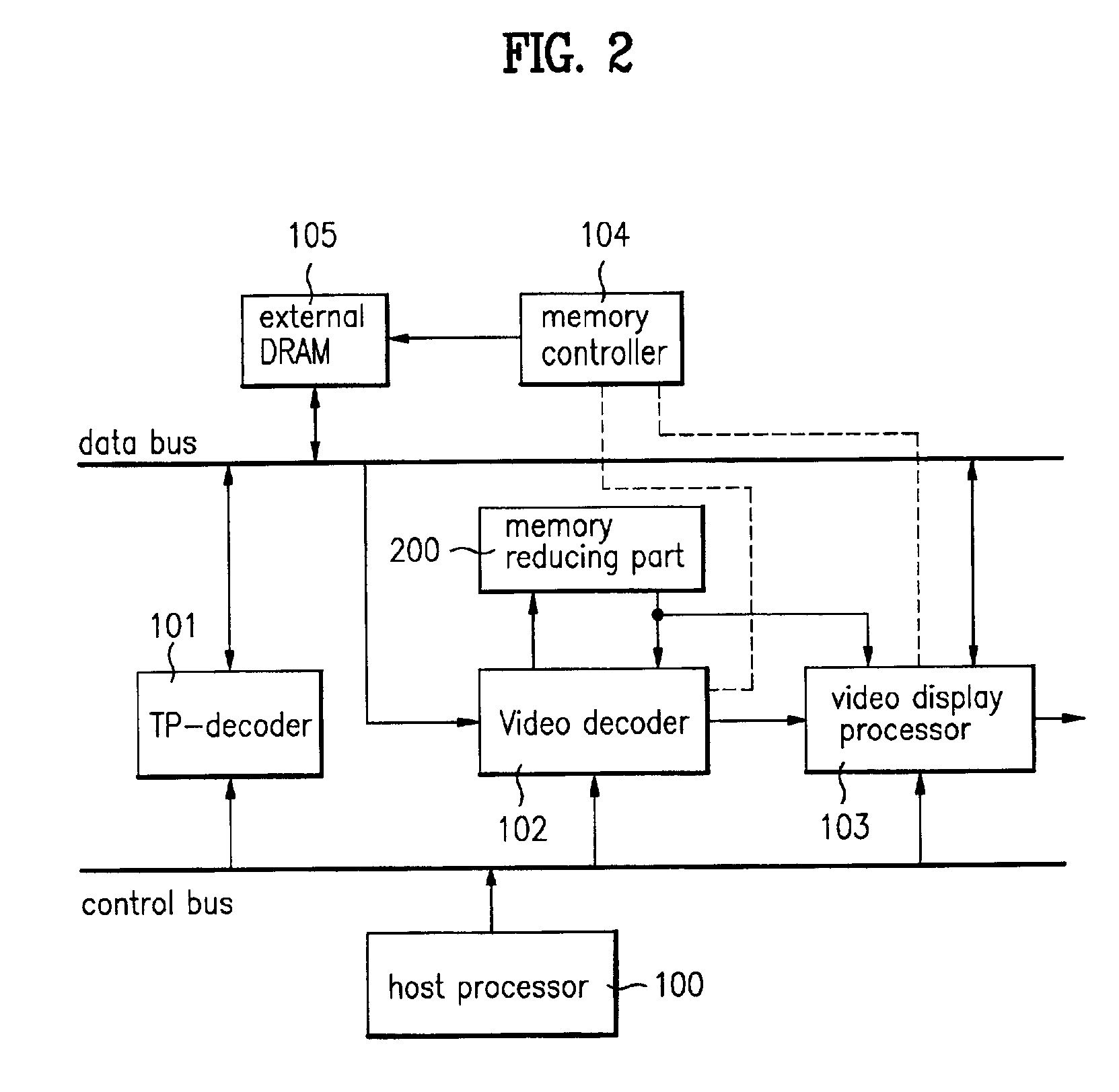
[0054]FIG. 2 shows a block diagram of an MPEG decoding system according to the present invention wherein a memory reducing part 200 is added to the structure in FIG. 1.

[0055]Referring to FIG. 2, the external memory 105 may include a general DRAM (dynamic random access memory) or a synchronous SRAM (static random access memory) for a high speed interface.

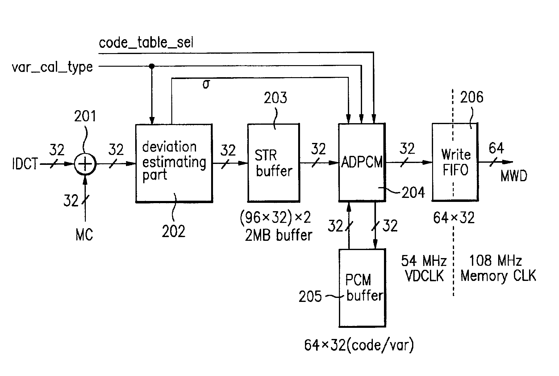
[0056]FIG. 3 shows in detail a block diagram of a memory reducing part 200 in FIG. 2.

[0057]Referring to FIG. 3, the memory reducing part 200 includes an adder 201 adding IDCT data in the video decoder 102 to motion compensated data, a deviation estimating part 202 calculating a standard deviation σ from an output signal of the adder 201, a STR (storage) buffer 203 storing an output of the adder 201 as a macro block unit, an ADPCM encoder 204 compressing the data stored in the...


PUM


Abstract

A memory reducing device in an apparatus for receiving moving pictures is applied to the fields such as a digital television receiver, a digital video conference system and the like. The memory reducing device enables to reduce an external memory of an MPEG-2 video decoding chip and obtain standard deviations by predicting the current pixel using a pixel located at the highly-related direction which is determined by having the deviation estimating part measure the relation between the horizontal or vertical direction of the pixels adjacent there between and to be currently encoded. Moreover, the memory reducing device enables to increase a compression ratio as well as provide clear distinction of high definition by reducing the difference less than the bit precision of the current pixel by means of predicting the current pixel by selecting the pixel located at the highly-related direction with the above same method and performing quantization with the prediction.

Description

BACKGROUND OF THE INVENTION[0001]1. Field of Invention[0002]The present invention relates to an apparatus for receiving moving pictures, and more particularly, to a memory reducing device in an apparatus for receiving moving pictures which is applied to the fields such as a digital television receiver, a digital video conference system and the like.[0003]2. Discussion of the Related Art[0004]As the digital television broadcasting becomes a major issue in that broadcasting field, many efforts have been contributed to compress video data to make a television receiver provide a clear distinction of high definition for watching television at home.[0005]MPEG-2 (moving picture expert group—2) is mainly used for an algorithm to compress the video signals. A compressing ration of the MPEG-2 ranges 1 / 40 to 1 / 60 which is a relatively large value.[0006]Algorithms such as MPEG-2 enables to transmit digital data of high definition which are usually difficult to be dealt with through general broa...

Claims


Application Information

Patent Timeline
Patent Type & Authority Patents(United States)
IPC IPC(8): G06T9/00H04N7/26H04N7/50H04N5/44
CPCH04N19/61H04N19/423H04N19/428H04N5/4401H04N21/426H04N19/124H04N19/137H04N19/182H04N19/426
Inventor KIM, EUNG TAECHUNG, TAE IL
Owner LG ELECTRONICS INC
Learn More