
Programmable photoelectric sensor and a system for adjusting the performance characteristics of the sensor

Inactive Publication Date: 2005-09-27
TRI TRONICS
View PDF9 Cites 62 Cited by
  • Summary
  • Abstract
  • Description
  • Claims
  • Application Information

AI Technical Summary

Benefits of technology

[0013]Another advantage of the present invention is that it allows the operator to monitor the actual response of the sensor on a contrast indicator built into the photoelectric sensor in the form of an LED array, or by utilizing a graphic display oscilloscope style contrast deviation analyzer. The contrast deviation analyzer charts the signal level deviation of the received signal against the background of the dynamic range of the sensor while monitoring on-going input events. This allows the operator to view the actual response of the sensor on a substantially real time basis, and adjust the performance parameters of the sensor to optimize sensor performance to the specific sensing task.
[0014]Yet another advantage of the photosensor of the present invention is that once the performance parameters are determined for a particular sensing task, these performance parameters can be stored in memory in the photosensor. As a result, if the sensor is utilized for multiple sensing tasks, the optimal performance parameters can be recalled from memory and utilized to control / program the sensor to restore the recalled performance parameters, thereby eliminating the need for the operator to re-perform the set-up process. It is noted that in one embodiment the sensor can only store one setting, and the computer is utilized to store any other previous settings. However, these previously stored settings can be downloaded to the sensor at any time.
[0015]Additional advantages of the present invention will become apparent to those skilled in the art from the following detailed description of exemplary embodiments of the present invention.

Problems solved by technology

However, there are many sensing environments and sensing tasks in which the determination of the proper sensor settings necessary to accurately and consistently identify the presence (or absence) of an object can not be easily performed.
For example, in certain low contrast detection scenarios, or in detection scenarios in which the object is subject to substantial vibration, it is often difficult to determine the sensor settings necessary for the sensor to repeatedly and accurately record each output event (e.g., detection of an object).
In other words, it is difficult to determine the optimal sensor settings for the given sensing environment.
This task of optimizing the sensor settings is further complicated by the increase in the number of features and parameters of today's photoelectric sensors, which are controllable / variable by the operator.
The optimization task is compounded by the fact that known photoelectric sensors did not provide much guidance to the operator with regard to the actual operation of the photoelectric sensor while performing a given sensing task.
However, no other information was provided to the operator.
If an operator was new, the adjustment process could require a significant trial and error process, and require a substantial amount of time.
Notwithstanding the ability of the photoelectric sensor of the '341 patent to provide contrast information during operation, the sensor lacks the ability to provide the operator with additional information that would expedite the adjustment process and allow for further optimization of the sensor settings.
For example, the sensor of the '341 patent does not provide any indication regarding whether or not the sensor is on the verge of operating in a saturation region (i.e., outside of the useful dynamic range of the sensor), which is something the operator attempting to adjust the sensor would need to be aware of.

Method used


Image

  • Programmable photoelectric sensor and a system for adjusting the performance characteristics of the sensor
  • Programmable photoelectric sensor and a system for adjusting the performance characteristics of the sensor
  • Programmable photoelectric sensor and a system for adjusting the performance characteristics of the sensor

Examples


Embodiment Construction

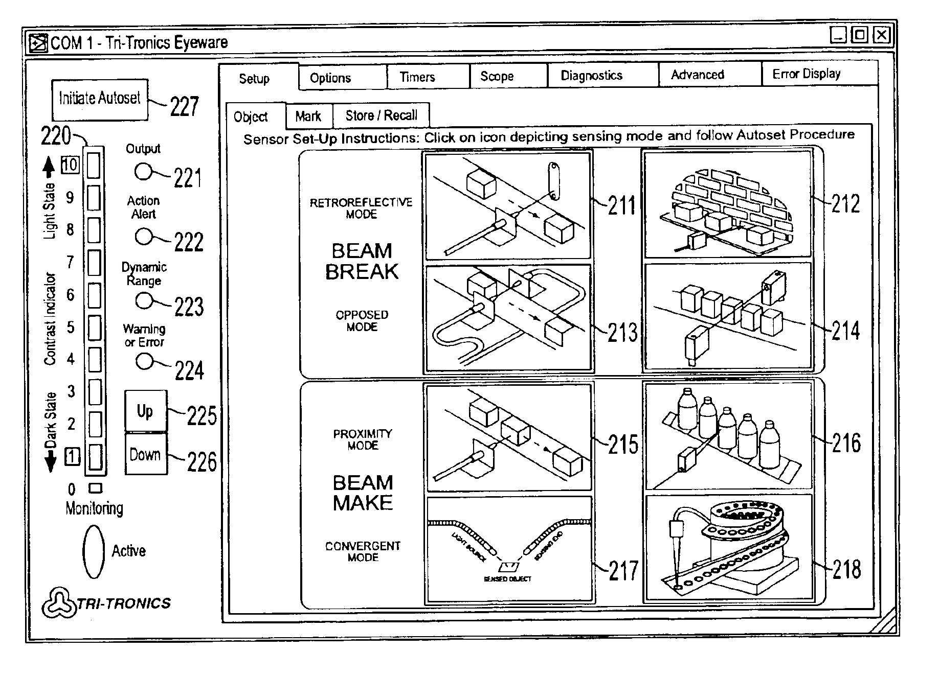
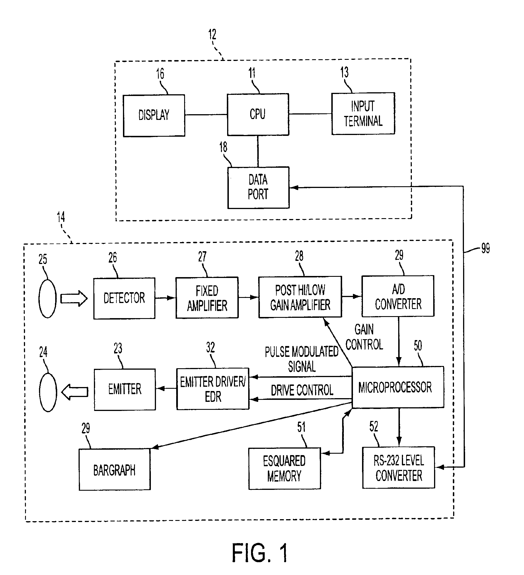
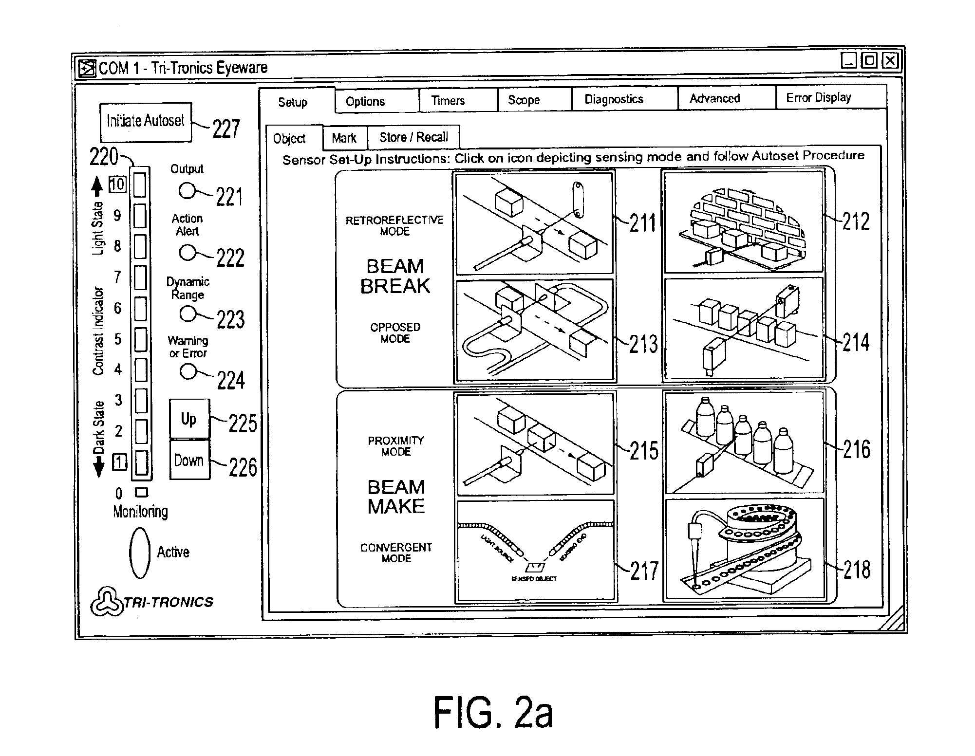
[0027]FIG. 1 illustrates an exemplary block diagram of the system of the present invention which includes a computer device 12 and the digitally controlled photoelectric sensor 14. Referring to FIG. 1, the computer device 12 includes a microprocessor / CPU 11, an operator input terminal 13 (e.g., keyboard, mouse, etc.), a display monitor 16 and a data port 18 capable of forwarding instructions / commands to the sensor 14, and receiving data from the sensor 14. In the exemplary embodiment of FIG. 1, the computer device communicates with the sensor via a serial data bus 99 employing the RS-232 standard. However, it should be noted that the present invention is not limited as such, and any other suitable communication link can be utilized.

[0028]Referring to the sensor 14, the sensor 14 comprises a variable current driver circuit 32 and an emitter light source 23, which is typically a light emitting diode (LED). A pulse modulated signal from a microprocessor 50 contained in the sensor is co...


PUM


Abstract

A programmable photoelectric sensor and a system for programming / controlling the photoelectric sensor and for monitoring the performance of the photoelectric sensor. The system includes a processor coupled to the photoelectric sensor, which is operative for generating at least one graphical user interface and for programming / adjusting the operation of the photoelectric sensor; and a display device coupled to the processor for displaying the graphical user interface. The processor programs / adjusts the operation of the photoelectric sensor in accordance with selections of an operator utilizing icons displayed on the graphical user interface.

Description

RELATED APPLICATIONS[0001]This application claims priority from U.S. Provisional Patent Application No. 60 / 299,441, filed Jun. 21, 2001, the disclosure of which is incorporated herein, in its entirety, by reference.FIELD OF THE INVENTION[0002]The present invention relates to a programmable, digitally controlled photoelectric sensor, and a system which allows an operator to easily adjust the sensor to a specific sensing task by viewing a simple, easy-to-use graphic display monitor and selecting (e.g., by clicking utilizing a computer mouse) icons representing the desired mode of operation. Upon selection of the desired mode of operation, the system automatically recalls the proper performance attributes / parameters (e.g., response time, hysteresis, autoset level, output mode, etc.) and programs / controls the sensor to operate in accordance with the recalled performance parameters. Once the set-up procedure is completed, the system allows the operator to monitor the response of the sens...

Claims


Application Information

Patent Timeline
IPC IPC(8): G01V8/10G01V13/00
CPCG01V8/10G01V13/00
Inventor WARNER, ROBERTSEEHAWER, SCOTTHACQUEBORD, DANIEL
Owner TRI TRONICS
Features
  • Generate Ideas
  • Intellectual Property
  • Life Sciences
  • Materials
  • Tech Scout
  • Unparalleled Data Quality
  • Higher Quality Content
  • 60% Fewer Hallucinations
Learn More