Method frame storage using multiple memory circuits

a memory circuit and method frame technology, applied in the field of computer systems, can solve the problems that the method invocation significantly affects the performance of the computing system, and achieve the effect of improving the speed of the method invocation

Inactive Publication Date: 2005-09-27
SUN MICROSYSTEMS INC
View PDF57 Cites 26 Cited by
  • Summary
  • Abstract
  • Description
  • Claims
  • Application Information

AI Technical Summary

Benefits of technology

[0013]Accordingly, the present invention provides a memory architecture to improve the speed of method invocation. Specifically, method frames are stored in two different memory circuits. The first memory circuit stores the execution environment of each method call, and the second memory circuit stores parameters, variables or operands of the method calls. In one embodiment, the execution environment includes a return program counter, a return frame, a return constant pool, a current method vector, and a current monitor address. In some embodiments, the memory circuits are stacks; therefore, the stack management unit can be used to cache either or both memory circuits.

Problems solved by technology

Typically, method invocation significantly impacts the performance of the computing system due to the excessive number of memory accesses method invocation requires.

Method used


Image

  • Method frame storage using multiple memory circuits
  • Method frame storage using multiple memory circuits
  • Method frame storage using multiple memory circuits

Examples


Embodiment Construction

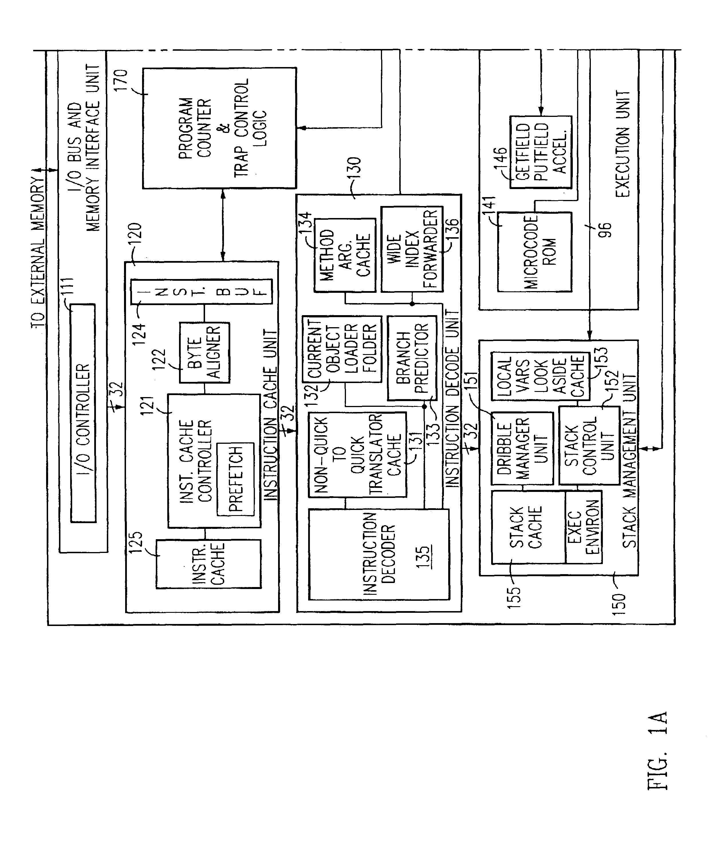
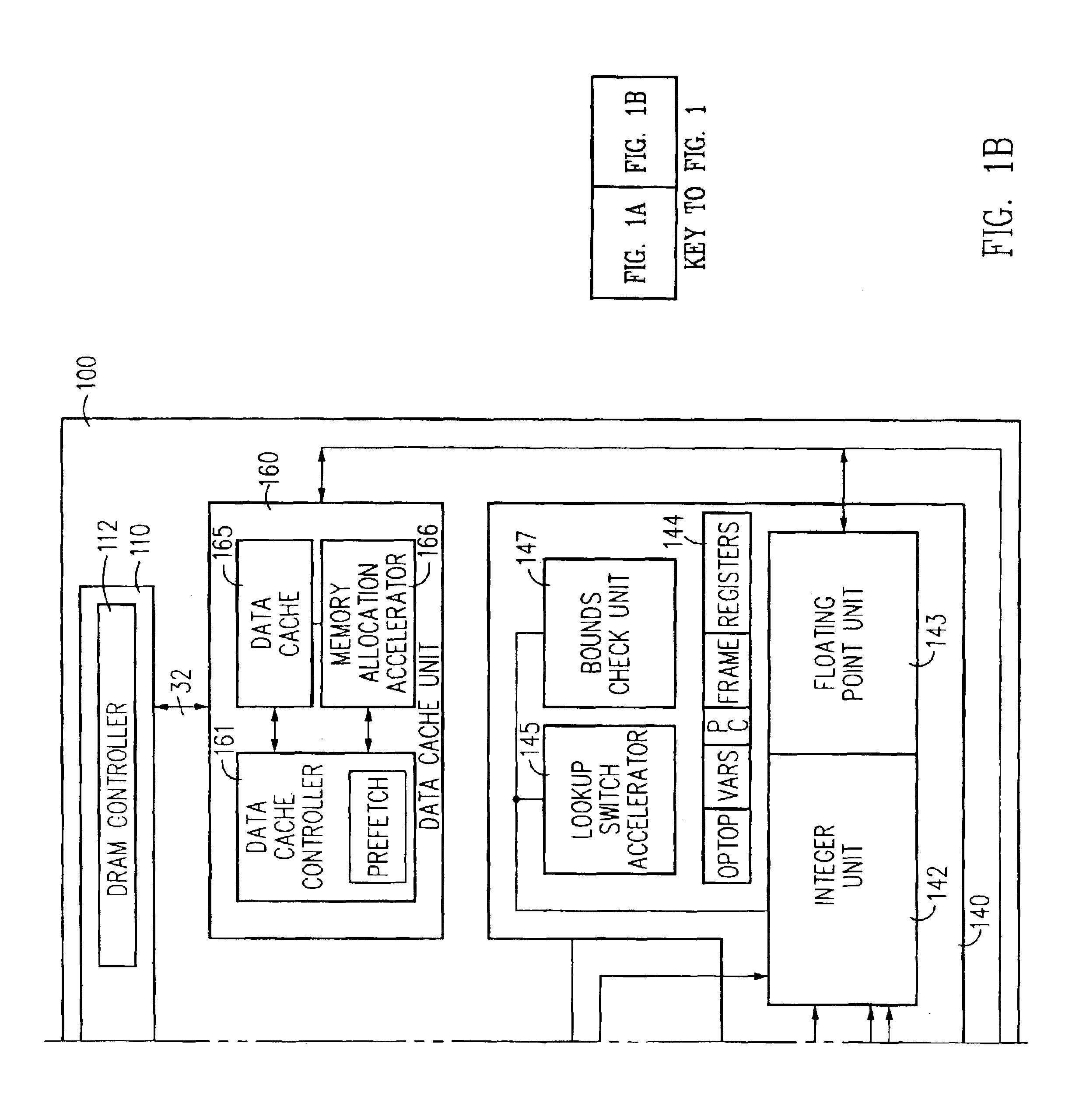
[0035]FIG. 1 illustrates one embodiment of a virtual machine instruction hardware processor 100, hereinafter hardware processor 100, that includes a memory architecture in accordance with the present invention to store method frames, and that directly executes virtual machine instructions that are processor architecture independent. The performance of hardware processor 100 in executing JAVA virtual machine instructions is much better than high-end CPUs, such as the Intel PENTIUM microprocessor or the Sun Microsystems ULTRASPARC processor, (ULTRASPARC is a trademark of Sun Microsystems of Mountain View, Calif., and PENTIUM is a trademark of Intel Corp. of Sunnyvale, Calif.) interpreting the same virtual machine instructions with a software JAVA interpreter. or with a JAVA just-in-time compiler; is low cost; and exhibits low power consumption. As a result, hardware processor 100 is well suited for portable applications. Hardware processor 100 provides similar advantages for other vir...


PUM


Abstract

A memory architecture in accordance with an embodiment of the present invention improves the speed of method invocation. Specifically, method frames of method calls are stored in two different memory circuits. The first memory circuit stores the execution environment of each method call, and the second memory circuit stores parameters, variables or operands of the method calls. In one embodiment the execution environment includes a return program counter, a return frame, a return constant pool, a current method vector, and a current monitor address. In some embodiments, the memory circuits are stacks; therefore, the stack management unit to cache can be used to cache either or both memory circuits. The stack management unit can include a stack cache to accelerate data transfers between a stack-based computing system and the stacks. In one embodiment, the stack management unit includes a stack cache, a dribble manager unit, and a stack control unit. The dribble manager unit includes a fill control unit and a spill control unit. Since the vast majority of memory accesses to the stack occur at or near the top of the stack, the dribble manager unit maintains the top portion of the stack in the stack cache. When the stack-based computing system is popping data off of the stack and a fill condition occurs, the fill control unit transfer data from the stack to the bottom of the stack cache to maintain the top portion of the stack in the stack cache. Typically, a fill condition occurs as the stack cache becomes empty and a spill condition occurs as the stack cache becomes full.

Description

RELATED APPLICATIONS[0001]This application is a continuation of U.S. patent application Ser. No. 08 / 787,617, filed Jan. 23, 1997, entitled “METHOD FRAME STORAGE USING MULTIPLE MEMORY CIRCUITS,” and naming James Michael O'Connor and Marc Tremblay as inventors, now U.S. Pat. No. 6,532,521, which is incorporated herein by reference in its entirety, and which claims the benefit of U.S. Provisional Application No. 60 / 010,527, filed Jan. 24, 1996, entitled “Methods and Apparatuses for Implementing the JAVA Virtual Machine” (JAVA is a trademark of Sun Microsystems, Inc.) and naming Marc Tremblay, James Michael O'Connor, Robert Garner, and William N. Joy as inventors, an is a continuation-in-part application of U.S. application Ser. No. 08 / 647,103, filed May 7, 1996, entitled “METHOD AND APPARATUS FOR STACK HARDWARE PARTITIONING FOR A STACK-BASED TYPE PROCESSOR” now abandoned naming James Michael O'Connor and Mark Tremblay as inventors and U.S. application Ser. No. 08 / 642,253, filed May 2, ...

Claims


Application Information

Patent Timeline
Patent Type & Authority Patents(United States)
IPC IPC(8): G06F11/00G06F9/00G06F3/00G06F9/34G06F9/30G06F9/318G06F9/345G06F9/40G06F9/42G06F9/44G06F9/455G06F12/08G06F15/78
CPCG06F9/30021G06F9/30134G06F9/30167G06F9/345G06F9/3802G06F9/443G06F9/45504G06F12/0875G06F15/7846G06F9/3017G06F9/264G06F9/30174G06F9/30145G06F9/45516G06F2212/451G06F9/449G06F9/30181G06F9/06
Inventor O'CONNOR, JAMES MICHAELTREMBLAY, MARC
Owner SUN MICROSYSTEMS INC
Why Eureka
Try Eureka