Grease removal system

Active Publication Date: 2005-10-04
ZURN INDS
View PDF15 Cites 34 Cited by
  • Summary
  • Abstract
  • Description
  • Claims
  • Application Information

AI Technical Summary

Benefits of technology

[0011]Another embodiment of the subject invention is directed to a grease removal system for removing grease having a grease trap tank wherein grease is accumulated upon the surface of other effluent within the tank. A discharge portal extends from the grease trap tank at a certain level on the tank to extract the accumulated grease. A replaceable container is used for collecting the grease extracted from the grease trap tank, wherein the replaceable container has an inlet. A quick connect coupling exists between the discharge portal and the replaceable container inlet for ease in removal or installation of the discharge portal with the replaceable container.

Problems solved by technology

The overtaxing of municipal sewage treatment facilities has become a serious problem in many communities and ordinances requiring a reduction in volume of grease and insoluble solids discharged into municipal sewers are becoming more widespread and stringent.
As the grease coating grows, it obstructs the flow of wastewater in the sewage pipe.
In many instances, grease traps are not properly cleaned or maintained which may result in inadequate removal of grease.
However, these compartmentalized grease traps typically utilize removable screens, level and temperature sensors, valves and heating devices to properly maintain the flow and separation of grease from the wastewater.
Cleaning of these grease traps is an unpleasant task that can become very messy and tedious.
However, if the grease trap is not properly maintained, the grease will collect on the sensors and valves, thereby causing the grease trap to function improperly.

Method used


Image

  • Grease removal system
  • Grease removal system
  • Grease removal system

Examples


Embodiment Construction

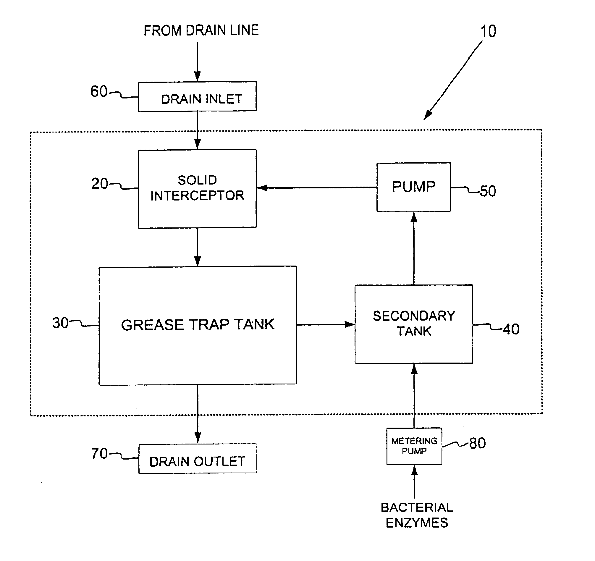
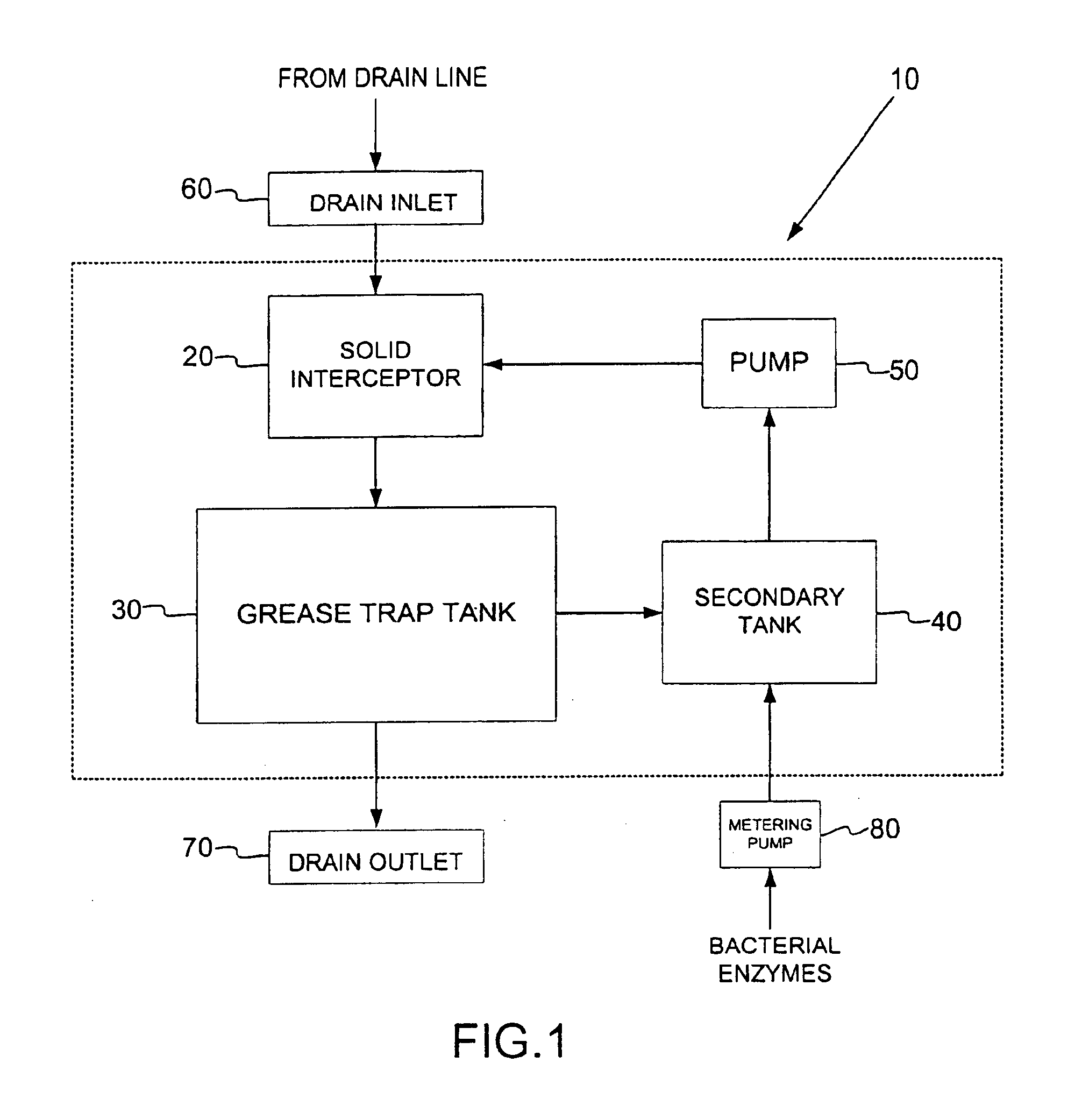
[0026]FIG. 1 shows a block diagram of a grease removal system 10 in accordance with the present invention. The grease removal system 10 is typically placed in line with a wastewater drain line such as in a drain line of a sink. Referring to FIG. 1, the grease removal system 10 includes a solid interceptor 20, a grease trap tank 30, a secondary tank 40, and a secondary tank pump 50. A drain inlet 60 may be fluidly coupled to the solid interceptor 20 for allowing wastewater to enter into the solid interceptor 20, wherein extraneous solid waste materials, such as food particles, plastic cups, straws, bits of paper, and other solid waste may be removed from the wastewater. The solid interceptor 20 may include a screen filter or bag that traps particles above a certain size. The wastewater from the solid interceptor 20 enters the grease trap tank 30 and the grease is separated from the wastewater. The grease trap tank 30 functions as a hold-up tank, wherein gravity is used to separate th...


PUM

PropertyMeasurementUnit
Fractionaaaaaaaaaa
Fractionaaaaaaaaaa
Weightaaaaaaaaaa

Abstract

A grease removal system includes a solid interceptor fluidly coupled to a grease trap tank, which is fluidly coupled to a secondary tank. The secondary tank contains an enzyme solution which biodegrades the grease. The grease removal system may also include a solid interceptor fluidly coupled to a grease trap tank which is fluidly coupled to a replaceable container. Grease is diverted from the grease trap tank into the replaceable container and thereafter discarded. The grease removal system may include a grease trap tank utilizing a unique arrangement of grease baffles and solids baffles which work together to isolate grease within a single region of the grease trap tank for ease of disposal. Finally, the grease removal system includes two level sensors which detect the level of grease within the grease trap tank and, at the appropriate level direct the accumulated grease from the grease trap tank.

Description

CROSS REFERENCE TO RELATED APPLICATIONS[0001]This application claims the benefit of U.S. Provisional Application No. 60 / 464,489, filed Apr. 22, 2003, U.S. Provisional Application No. 60 / 457,206, filed Mar. 25, 2003, and U.S. Provisional Application No. 60 / 500,399, filed Sep. 5, 2003, which are incorporated by reference in their entirety.BACKGROUND OF THE INVENTION[0002]1. Field of the Invention[0003]The present invention relates to the treatment of wastewater products and, more particularly, to a grease trap design for minimizing the disposal of grease, fats and oils from wastewater.[0004]2. Description of Related Art[0005]Grease traps are typically located in restaurants, meat and poultry processing plants, slaughter houses and other industries having excessive amounts of greasy wastewater and foreign materials, such as insoluable solids, that must be treated to prevent the discharge into sanitary sewer systems. The overtaxing of municipal sewage treatment facilities has become a s...

Claims


Application Information

Patent Timeline
IPC IPC(8): B01D17/025C02F1/40B01DB01D17/00B01D17/12B01D21/00B01D24/00B01D29/00B01D35/00C02F1/00C02F3/00C02F9/00E03F5/16
CPCB01D17/005E03F5/16B01D17/0208B01D17/0211B01D17/0214
Inventor TRIPODI, JOSEPHNICOLIA, CARL R.WROBLEWSKI, DOUGLAS R.BURNHAM, ROBERT J.
Owner ZURN INDS
Why Eureka
Try Eureka