Wind energy conversion system

a conversion system and wind energy technology, applied in the direction of wind energy generation, wind motors with parallel air flow, wind power systems with perpendicular air flow, etc., can solve the problems of limiting the cost-effectiveness and acceptance of wind power systems as viable options, wind power systems of excessive weight and cost, and wind power systems of over 33 tons. , to achieve the effect of reducing or increasing the size of the air gap, and increasing the drag for

Inactive Publication Date: 2005-10-04
WECS
View PDF35 Cites 175 Cited by
  • Summary
  • Abstract
  • Description
  • Claims
  • Application Information

AI Technical Summary

Benefits of technology

[0019]The present invention has as another object to provide a wind energy conversion system of reduced weight, mass and cost.
[0021]Additionally, it is an object of the present invention to adjust the size of the air gap between a stator and a rotor carried by a blade assembly for rotation past the stator to control the rotational speed of the blade assembly in a wind energy conversion system.
[0028]The present invention has as another object to balance the torques produced by counter-rotating wind turbines of a wind energy conversion system to avoid net torque being exerted on a tower supporting the wind turbines in an elevated position above the ground.
[0031]Some of the advantages of the present invention are that the wind energy conversion system may include one or more than one wind turbine, each having a blade assembly; the blade assemblies do not drive a drive shaft as in prior wind turbine systems; the weight of the wind energy conversion system is greatly reduced permitting lighter and less expensive guyed towers, stabilized by guy cables, to be used to support the one or more wind turbines in an elevated position above the ground; optimum performance versus cost and weight may be accomplished by varying the size of a center void and spinner for the blade assemblies; the air intake opening is maintained facing into the oncoming wind without the need for power consuming equipment and / or computers to direct yaw; intake air is deflected by the spinner toward the effective blade area of the one or more wind turbines; blade structure is eliminated from the short radius, low torque position where virtually no power is produced, thusly resulting in greater efficiency and decreased weight; exhaust air is discharged from the one or more wind turbines with greater efficiency, less back pressure on the one or more wind turbines and enhanced laminar air flow; the wind energy conversion system allows the commutators and brushes associated with conventional generators and which require maintenance and downtime to be eliminated; wind turbines of larger generating capacities can be supported at higher elevations to the advantage of greater wind speeds; greater power output is obtained using less air space than prior wind turbine systems; the wind energy conversion system can be used to generate DC or AC power; a greater number of wind energy conversion systems can be deployed per acre of land than conventional wind turbine systems; each stator may comprise a continuous stator element or a plurality of individual stator elements; each rotor may comprise a variable number of rotor elements; the blades of the blade assemblies have an airfoil configuration and are optimally sized in relation to spaces between the blades; a rudder assembly operates in conjunction with the intake hood to produce positive yaw on the hood; the exhaust plenum is configured to create a vacuum at the outlet opening; the outer rims of the blade assemblies are supported and positioned between cooperating rollers; electric power produced by the one or more wind turbines may be stored in batteries, which may be charged under control of a charging controller; the torque created by each wind turbine can be monitored in various ways; mild compression in the hood increases the velocity of the air through the turbines, thereby enhancing output at lower input wind speeds; the exhaust plenum may be designed to assist directional yaw; operation of the water misters may be controlled so that only water misters located adjacent the air intake opening are turned on; and output from the water misters may be controlled in accordance with the electrical output of the one or more wind turbines.

Problems solved by technology

This approach has resulted in wind power systems of excessive weight and cost, which has limited the cost-effectiveness and acceptance of wind power systems as a viable option for electric power production.
As an example, a 500 KWe Vesta V39 wind power system typically weighs over 33 tons and costs more than $1,000,000 installed.
Consequently, the use of wind as a renewable energy source has not been taken full advantage of, and the wind power industry has not realized its full potential.
Increasing the drive shaft speed to drive a generator requires a large, costly and heavy gear step-up transmission assembly.
The generator, weighing several tons, also contributes significant weight to the wind turbine system.
The excessive weight of conventional wind turbine systems necessitates a massive and costly tubular steel tower to support the propellers in an elevated position above the ground.
One drawback to these positioning systems is that they shut down under the highest potential power output conditions.
The Honnef patent does not disclose two blade assemblies each capable of producing an electrical output independently.

Method used


Image

  • Wind energy conversion system
  • Wind energy conversion system
  • Wind energy conversion system

Examples


Embodiment Construction

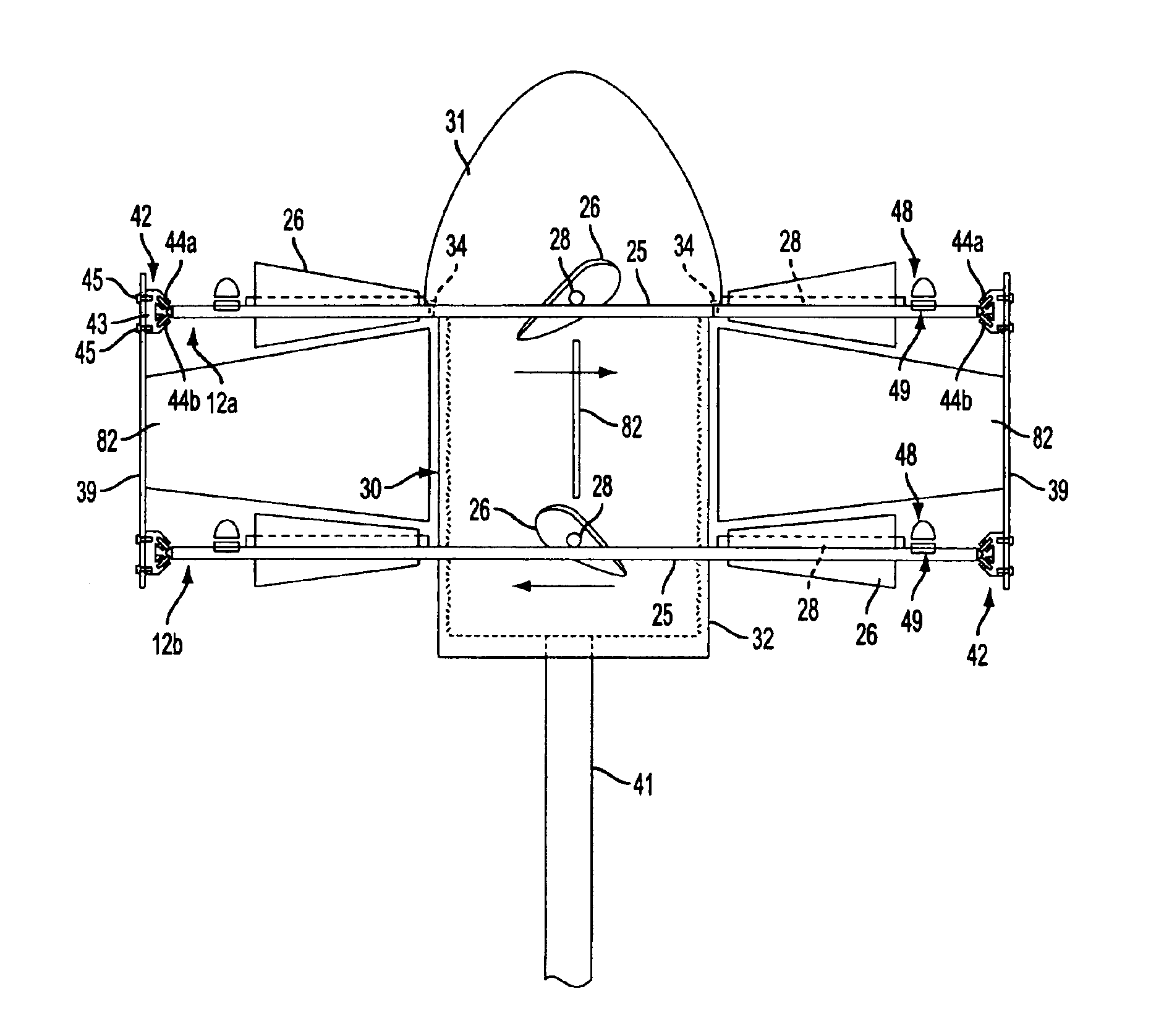
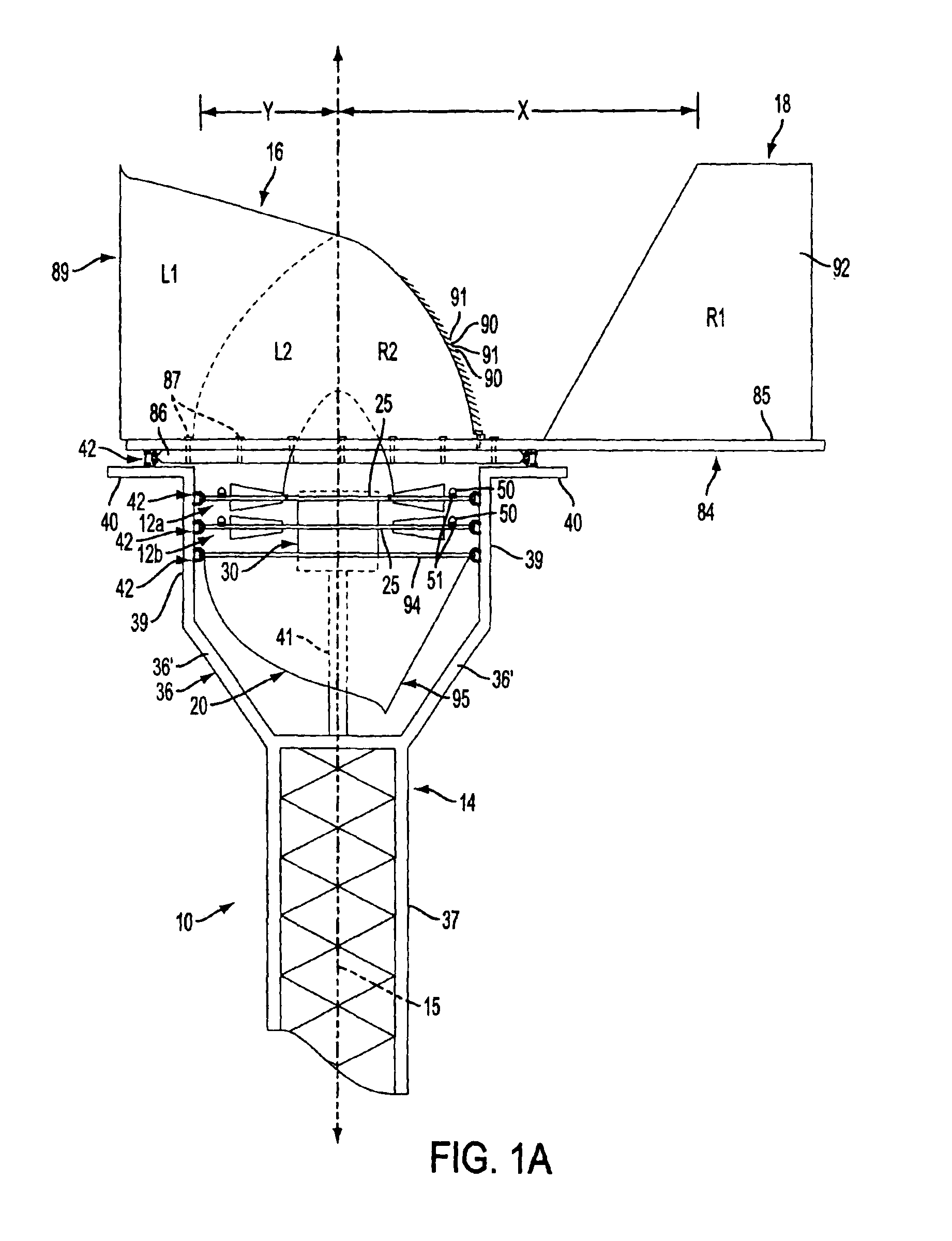
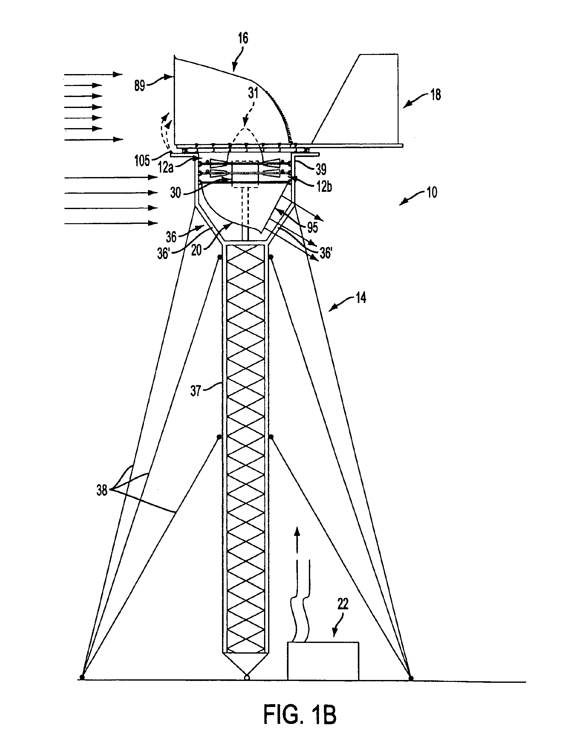
[0058]A wind energy conversion system or wind power system 10 according to the present invention is illustrated in FIGS. 1A and 1B and comprises upper and lower wind turbines 12a and 12b forming an electrical generator, a tower 14 supporting the wind turbines 12a and 12b at an elevated position above the ground for rotation about a vertical rotation axis 15, an air intake hood or snorkel 16 disposed over the upper wind turbine 12a for directing intake air to the wind turbines, a rudder assembly 18 for positioning the hood 16, and an exhaust plenum 20 disposed beneath the lower wind turbine 12b for exhausting air from the wind turbines. Although the wind energy conversion system 10 is shown as comprising upper and lower wind turbines 12a and 12b, it should be appreciated that the wind energy conversion system may comprise a single wind turbine, such as wind turbine 12a or 12b, forming the electrical generator as disclosed in prior provisional patent application Ser. No. 60 / 448,355 fi...


PUM


Abstract

A wind energy conversion system includes upper and lower wind turbines having counter-rotating blade assemblies supported for rotation about a vertical rotation axis, with each blade assembly carrying a rotor for rotation past a stator to produce an electrical output. The wind turbines are supported by a tower at an elevated position above the ground. Each wind turbine produces torque, and the wind energy conversion system provides for balancing the torques to avoid a net torque on the tower. Adjustment mechanisms are provided for adjusting blade pitch and for adjusting the size of an air gap between a stator and a rotor that comes into alignment with the stator as the rotor rotates therepast. The wind energy conversion system provides a hood for supplying intake air to a wind turbine and an exhaust plenum for exhausting air from the wind turbine, with the hood and the exhaust plenum being directionally positionable.

Description

CROSS-REFERENCE TO RELATED PATENT APPLICATION[0001]This application is a continuation-in-part of prior U.S. patent application Ser. No. 10 / 783,413 filed Feb. 20, 2004, which claims priority from prior provisional patent application Ser. No. 60 / 448,355 filed Feb. 20, 2003, the entire disclosures of which are incorporated herein by reference.BACKGROUND OF THE INVENTION[0002]1. Field of the Invention[0003]The present invention relates generally to wind energy conversion systems in which kinetic energy of wind is converted into electric power and, more particularly, to wind energy conversion systems having blade assemblies carrying rotor elements for movement past stator elements to produce electric current.[0004]2. Brief Discussion of the Related Art[0005]Current wind power technology has primarily been developed by adapting or modifying non-wind technologies to wind power applications. This approach has resulted in wind power systems of excessive weight and cost, which has limited the...

Claims


Application Information

Patent Timeline
Patent Type & Authority Patents(United States)
IPC IPC(8): F03D1/00F03D1/02F03D1/04
CPCF03D1/025F03D1/04F03D3/005F03D3/02F03D3/0472H02K7/1869H02K21/025Y02E10/72Y02E10/74H02K21/026F03D13/20F03D9/11F03D9/25Y02E70/30
Inventor MCCOIN, DAN KEITH
Owner WECS
Why Eureka
Try Eureka