
Method and system for graphics rendering using captured graphics hardware instructions

a graphics hardware and instruction technology, applied in the field of computer graphics systems, can solve the problems of consuming significant portions of processor time and system memory, requiring complex, realistic images to be rendered in color, and requiring color rendering of complex images, etc., and achieve the effect of reducing the memory requirements of the system

Inactive Publication Date: 2005-10-04
IBM CORP
View PDF26 Cites 39 Cited by
  • Summary
  • Abstract
  • Description
  • Claims
  • Application Information

AI Technical Summary

Benefits of technology

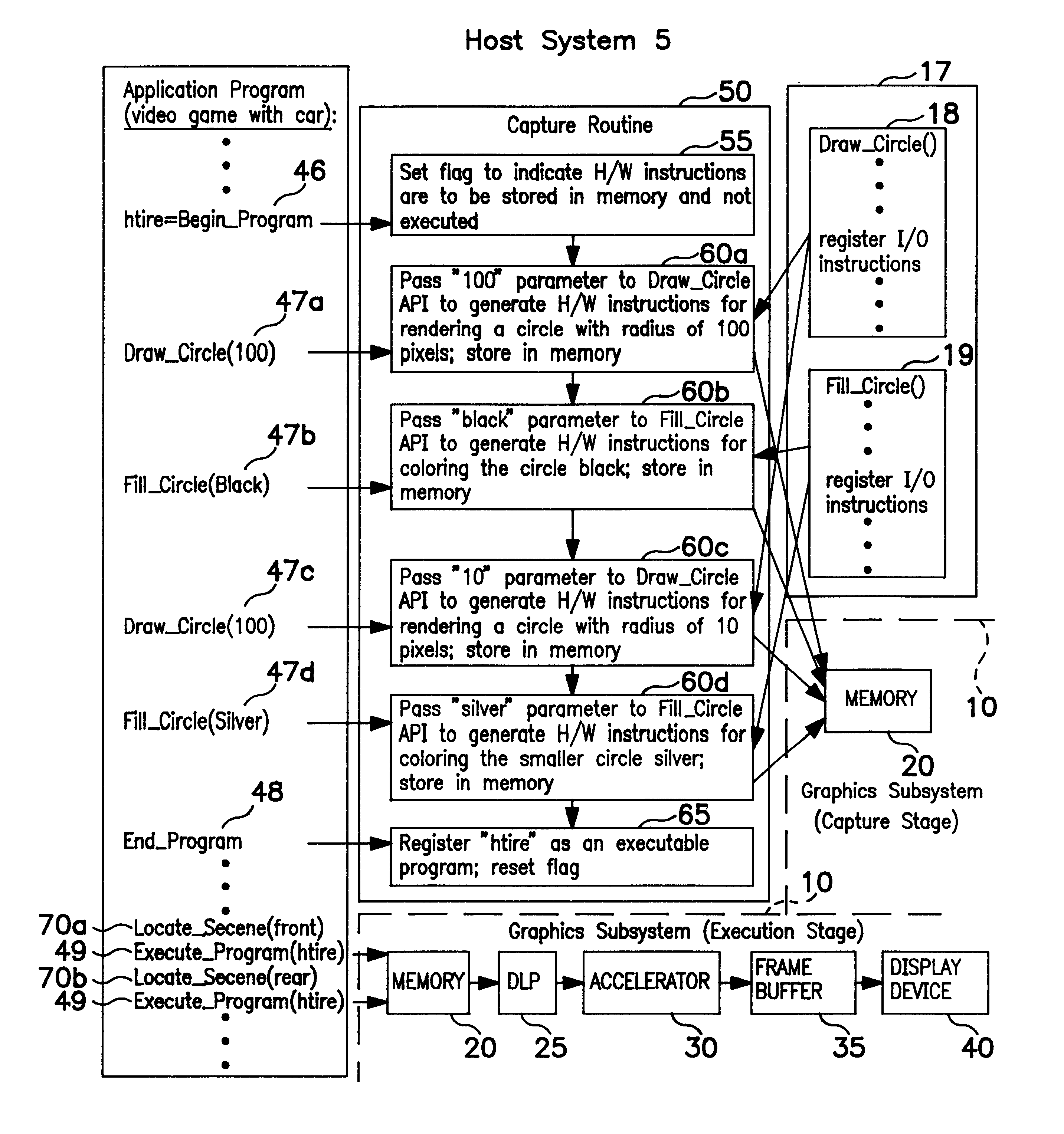
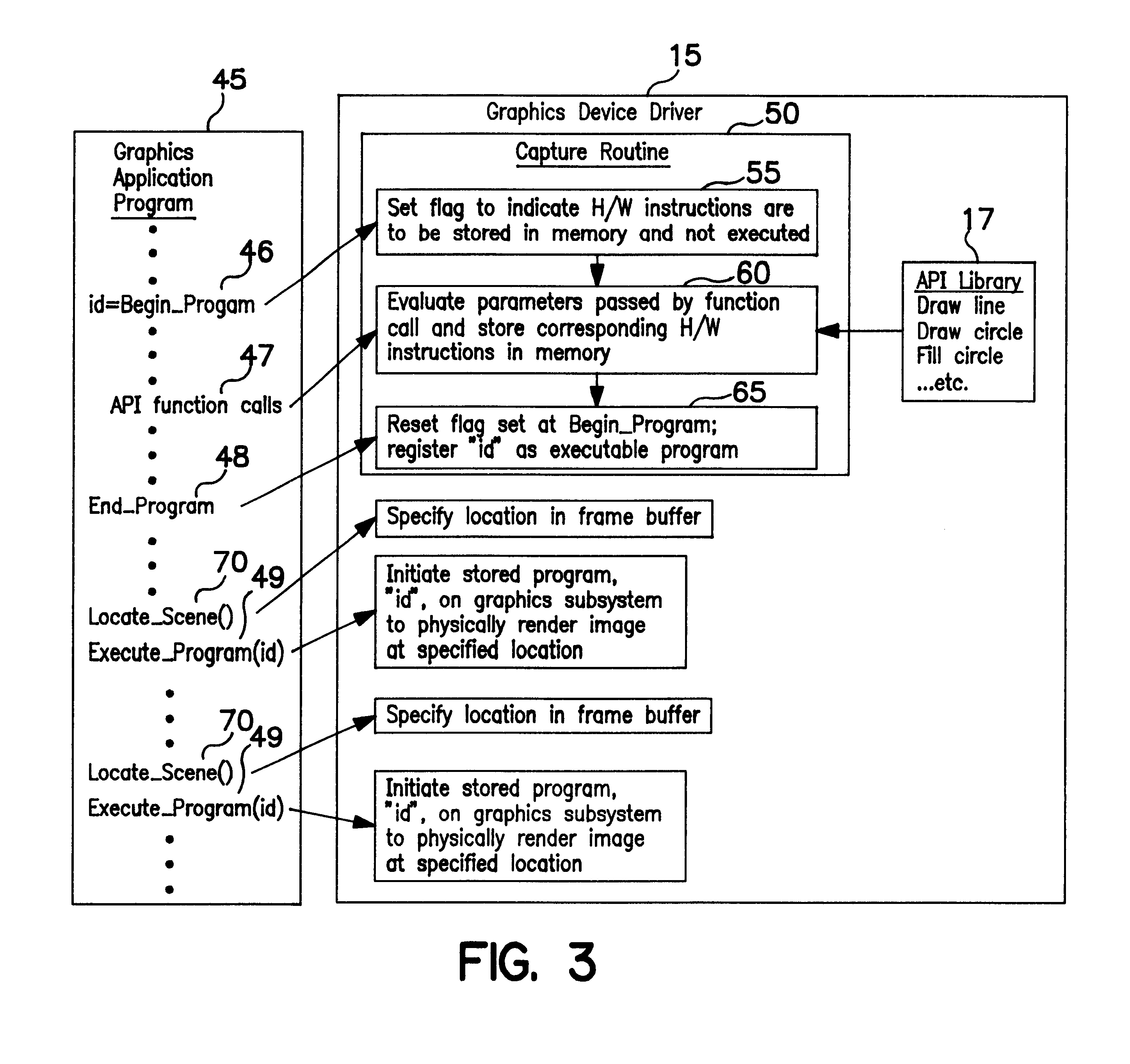
The present invention provides a method and system for offloading rendering tasks from a host processor to a graphics subsystem which can perform the rendering tasks on demand. This is achieved by capturing the hardware instructions to graphics hardware generated by the basic rendering functions called by a graphics application program and storing them in memory. When the application program requires the image to be rendered, it can execute the stored hardware instructions within the graphics subsystem to render the image, with only nomimal host processor operations being required. This results in conserved host processor cycles and reduced system memory requirements.

Problems solved by technology

Even with simple images, these tasks can consume significant portions of processor time and system memory.
However, graphics applications are becoming increasingly more sophisticated, requiring complex, realistic images to be rendered in color, with lighting, shadow and the like.
If certain images are required to be generated repetitively, for example, in the case of a video game, the high demands on processor time and system memory can slow image rendering and frustrate users.

Method used


Image

  • Method and system for graphics rendering using captured graphics hardware instructions
  • Method and system for graphics rendering using captured graphics hardware instructions
  • Method and system for graphics rendering using captured graphics hardware instructions

Examples


Embodiment Construction

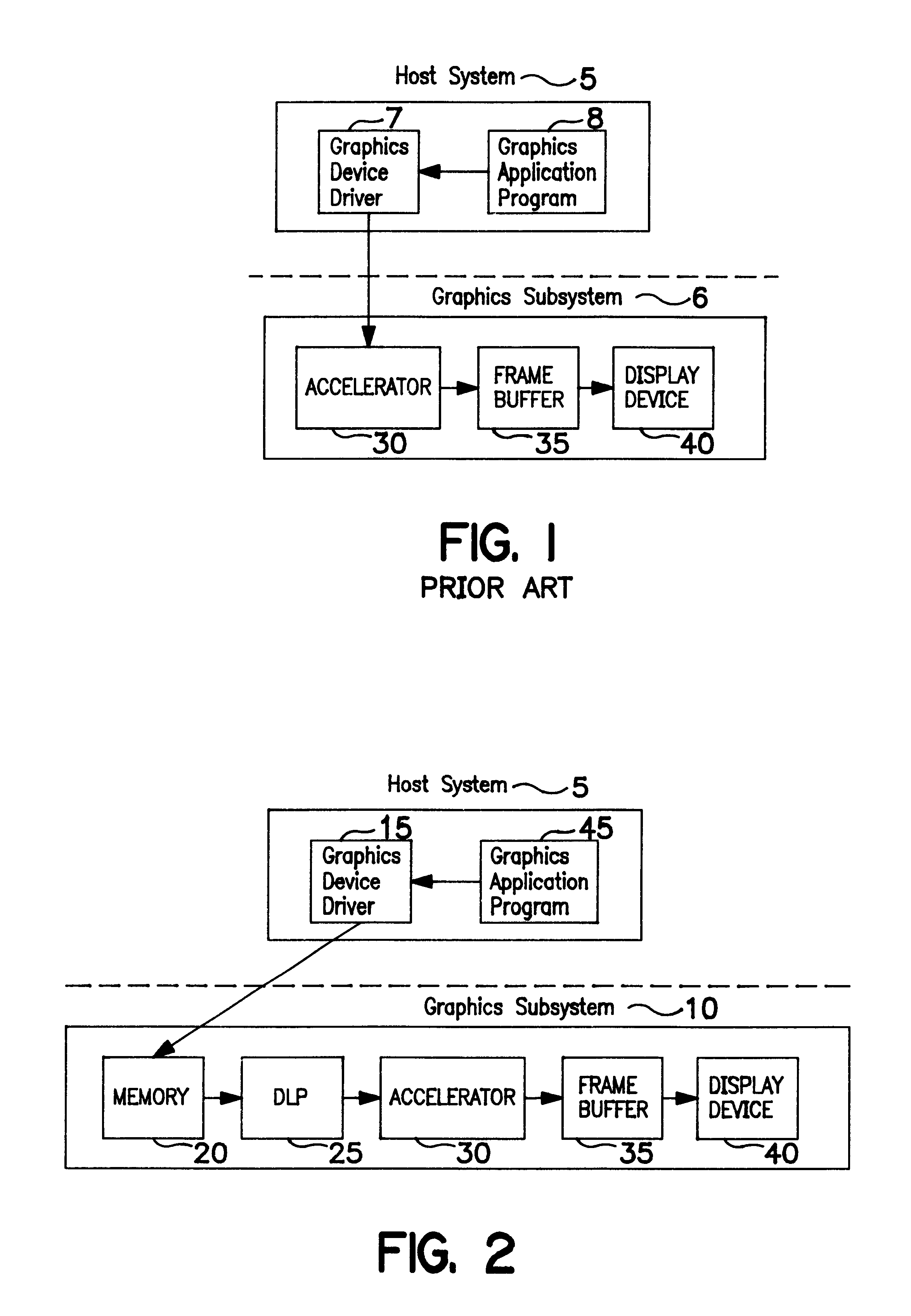
[0017]FIG. 1 illustrates a conceptual overview of a prior art graphics rendering system. In the system shown in FIG. 1, a host operating system 5 has graphics device driver software 7, which, in response to high-level graphics rendering specifications in graphics application program 8, issues low-level instructions to graphics accelerator 30 in graphics subsystem 6. Under the control of the graphics device driver 7, accelerator 30 writes pixel definitions to frame buffer 35, which are scanned onto display device 40 to physically render an image.

[0018]By contrast, FIG. 2 shows basic software and hardware components in a method and system for graphics rendering according to the present invention. Elements include a graphics subsystem 10 comprising a random access memory 20, a custom graphics processor known as Display List Processor (DLP) 25, an accelerator 30, a frame buffer 25, and a display device 40, such as a CRT. The DLP 25 is capable of fetching hardware instructions stored in ...


PUM


Abstract

A computer-implemented method and system for performing graphics rendering on demand on a graphics subsystem, with only nominal host system operations being required. An application program requiring graphics to be rendered is coded to bound a sequence of calls to basic rendering functions, defining a desired image to be rendered, between begin-program and end-program identifiers. When the application program is executed on a host operating system, a begin-program identifier invokes a function in a graphics device driver in the host system. The function captures the calls to the rendering functions within the application program in a memory as hardware instructions to the graphics subsystem. When the function encounters an end-program identifier, it registers the captured hardware instructions with the host system as an executable program. Subsequently, the application may render the image upon demand by calling the registered executable program, which will execute from the memory on the graphics subsystem, with only nomimal host processor operations being required. Thus, host processor operations and memory normally required for performing graphics rendering are conserved.

Description

CROSS REFERENCE TO RELATED APPLICATIONS[0001]Application Ser. No. 09 / 283,397 filed on even date herewith, assigned to International Business Machines Corporation, and having common inventorship.BACKGROUND OF THE INVENTION[0002]The present invention relates to computer graphics systems, and in particular to a method and system for increasing graphics rendering speed and efficiency by offloading rendering operations from a host processor onto a register-based graphics subsystem which can perform graphics rendering on demand with only nominal host processor operations being required.[0003]Generally, computer graphic images are produced by transferring pixel definitions (intensity and color), stored in a memory location known as a frame buffer, to a display screen. Presently, most display systems are raster-based, which means that a value stored in the frame buffer determines the intensity and color of an electron beam at a given pixel, as the beam scans the phosphor-coated inner surfac...

Claims


Application Information

Patent Timeline
Patent Type & Authority Patents(United States)
IPC IPC(8): G06T1/60G06F9/45G06K9/20G06F17/00G06T11/00G06T1/00G06T15/00G06F9/44
CPCG06T15/005G06T11/00
Inventor DEVINS, ROBERT J.SCHANELY, PAUL M.
Owner IBM CORP
Learn More