
Tantalum capacitor case with increased volumetric efficiency

Active Publication Date: 2005-10-04
TANTALUM PELLET CO LLC
View PDF5 Cites 35 Cited by
  • Summary
  • Abstract
  • Description
  • Claims
  • Application Information

AI Technical Summary

Benefits of technology

[0009]The present invention may be readily adapted to a variety of capacitors, capacitor materials and methods of creating capacitors. Embodiments of the present invention may provide a longer lasting capacitor, a capacitor that is more resistant to shock and vibration, and a capacitor that is easier to manufacture, among other benefits.
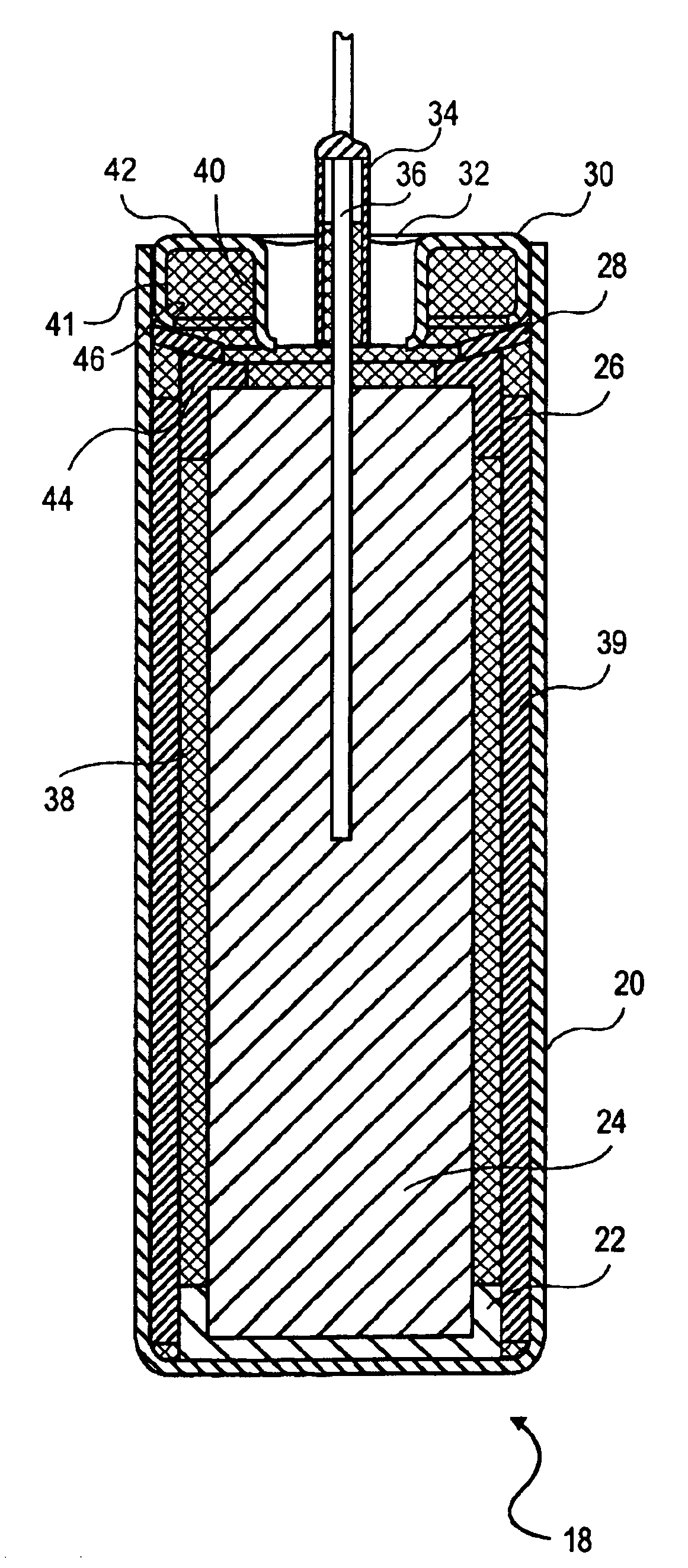
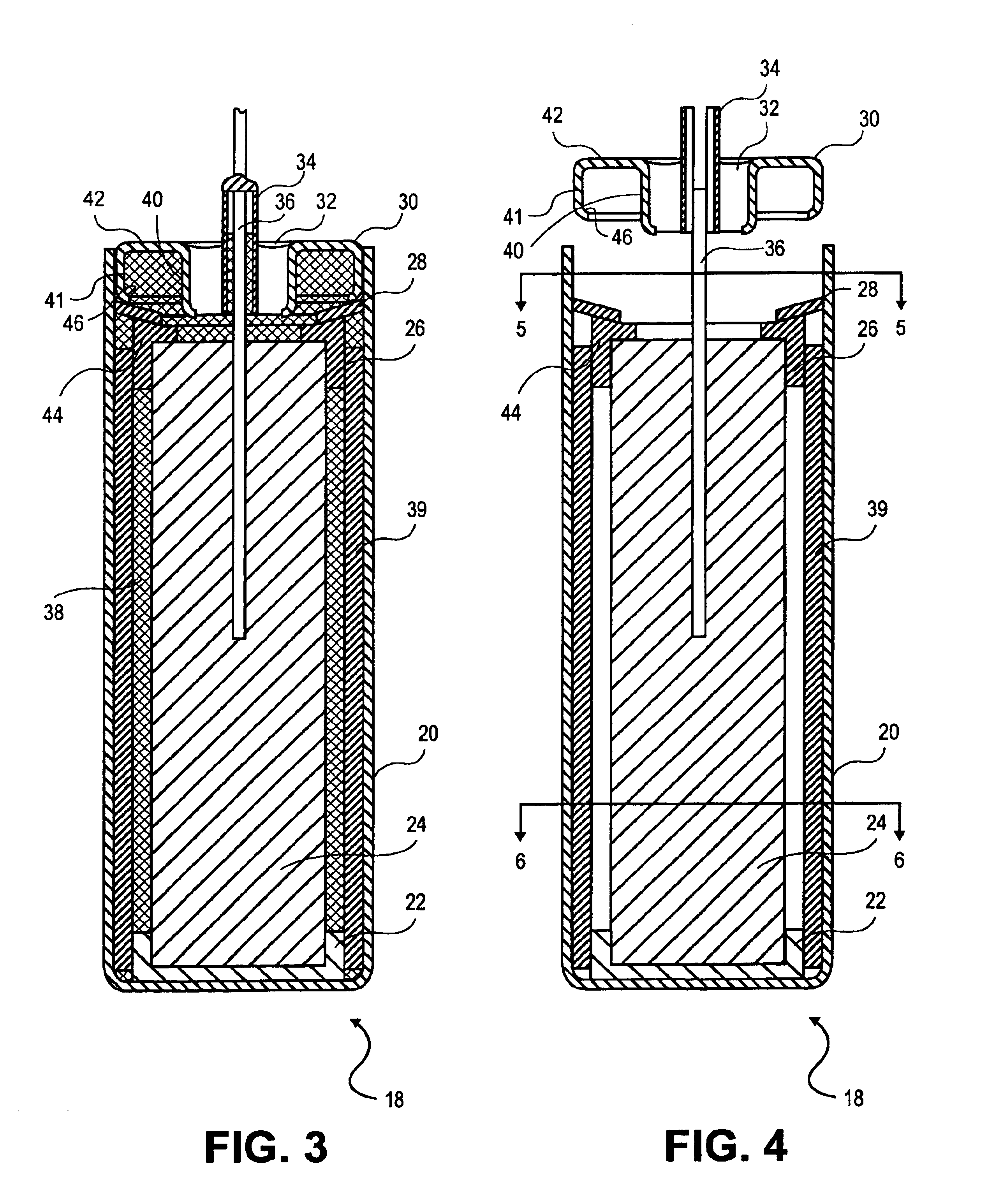
[0015]This capacitor design has many innovations that provide advantages over conventional wet tantalum capacitors. The cap shape allows extra electrolyte, cathode material or other material beneficial to the operation of the capacitor (for example a hydrogen absorbent material like Tantalum) to fill the empty spaces in the cap, and also allows for the cap to be attached so that the weld can run along the top of the case. Running the weld along the top of the case means that the assembly process for this capacitor is easily automated. Many conventional capacitors have a weld that runs around the side of the capacitor case. In order to create this weld, the case must either be turned on its side or the welding device must approach the case horizontally and then the case or the welding device must rotate and no more than one capacitor can be welded at a time. Embodiments of the present invention may include a weld that runs around the top and therefore the welding device approaches vertically and simply makes a circle around the top of the case. This allows an entire tray of capacitors to be welded while in the tray instead of welding each capacitor individually. The washer provides added strength to the capacitor to withstand external force and better supports the tantalum anode. The cap design also creates more room for electrolyte or other material in the case, prolonging the life of the capacitor.

Problems solved by technology

Therefore, the more electrolyte that is available for use in the case, the longer the life of the capacitor will be.
In the traditional capacitors, the cap or the combination of the cap and plug take up room inside the case, thereby reducing the amount of room available for electrolyte in the case.

Method used


Image

  • Tantalum capacitor case with increased volumetric efficiency
  • Tantalum capacitor case with increased volumetric efficiency
  • Tantalum capacitor case with increased volumetric efficiency

Examples


Embodiment Construction

[0025]It will be understood by those of ordinary skill in the art that the invention is not limited to the specific components and assembly procedures disclosed herein. Many additional components and assembly procedures known in the art consistent with the intended capacitor and / or assembly procedures for a capacitor will become apparent for use with embodiments of the present invention from the disclosure herein. Accordingly, for example, although particular hardware is disclosed, such hardware and implementing components may comprise any shape, size, style, type, model, version, measurement, concentration, material, quantity, and / or the like as is known in the art for such hardware and implementing components, consistent with the intended operation of assembling a capacitor. It will also be understood by those of ordinary skill in the art that the invention is not limited to use of any specific components, provided that the components selected are consistent with the intended capa...


PUM

PropertyMeasurementUnit
Forceaaaaaaaaaa
Shapeaaaaaaaaaa
Widthaaaaaaaaaa

Abstract

A capacitor and a method for assembling a capacitor. A capacitor is assembled from a case, which contains an anode that is electrically insulated from the case by isolators. A washer is placed above the anode. This washer transfers force from a capacitor cap to the isolators and anode, securing the anode in place. A cap is placed on the case. The cap may be shaped as a toroid with an outer and an inner annular wall. The annular walls may meet at the top and have an opening at the bottom creating a cap cavity in order to store electrolyte or other materials in the cap. The cap also supports a glass seal that insulates the lead tube and lead wire coming from the anode. Once assembled, the capacitor is filled with electrolyte. A weld extends around the cap to secure the cap to the case. The weld may be administered from the top of the capacitor.

Description

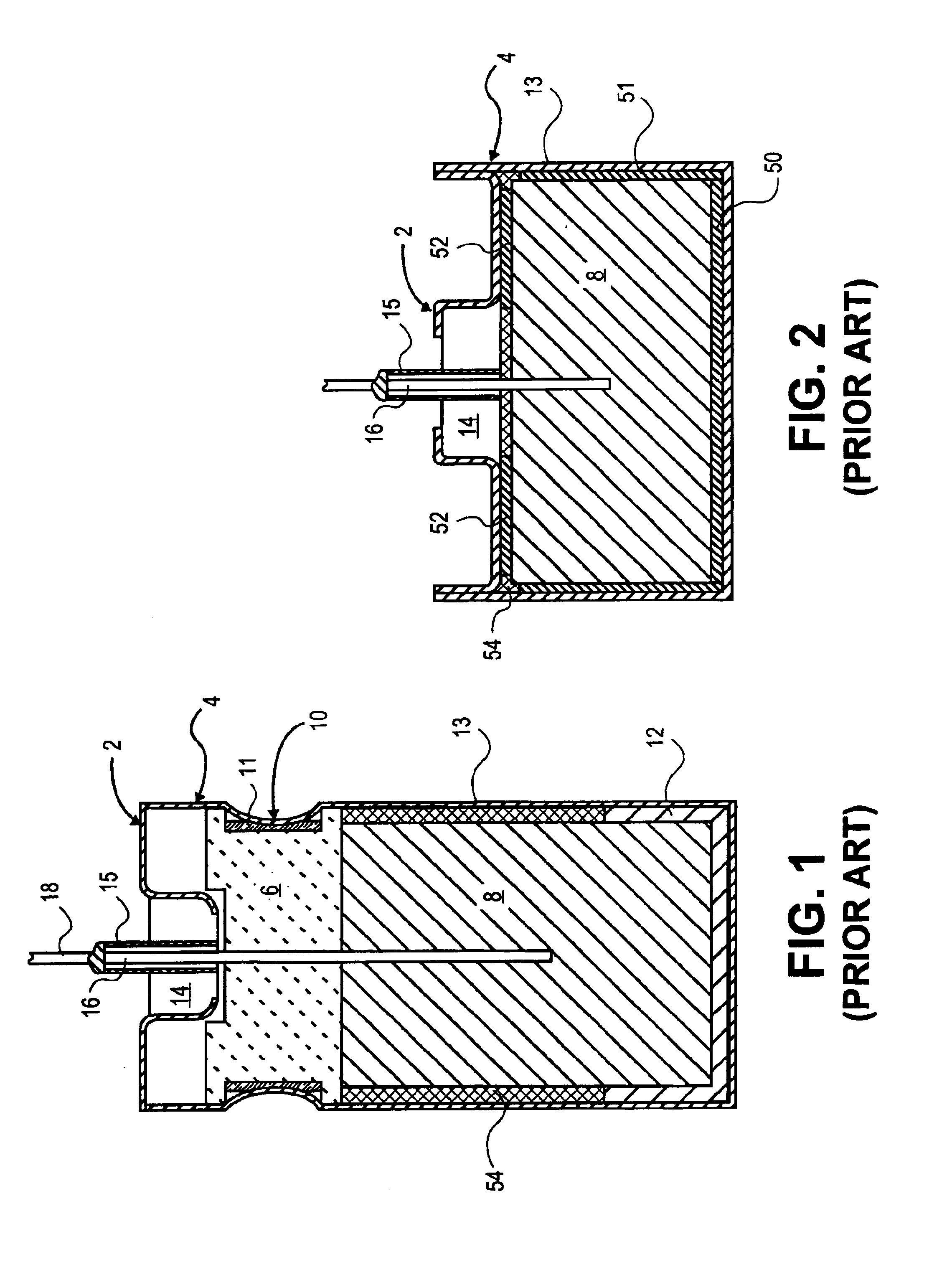
BACKGROUND OF THE INVENTION[0001]1. Technical Field[0002]This invention generally relates to a tantalum capacitor case that increases the electrolyte volume of the standard size case, and to a method for assembling the tantalum capacitor.[0003]2. Background Art[0004]There are at least two common conventional tantalum electrolytic capacitor configurations. The first configuration is illustrated by FIG. 1. The capacitor assembly is contained in a case 13 having a height greater than its diameter. The case 13 contains an isolator 12, which is formed from an electrically insulative material and is shaped so that it may receive a tantalum anode 8. The isolator 12, as shown in FIG. 1, is a flat disk of insulative material that sits under the anode 8 and prevents the anode 8 from coming into contact with the case 13. The isolator 12 also comprises a ring of insulative material that fits down around the sides of the anode 8. The isolator 12 may also be arranged so that legs on the isolator ...

Claims


Application Information

Patent Timeline
IPC IPC(8): H01G9/00H01G9/042H01G9/06H01G9/10
CPCH01G9/042H01G9/10H01G9/06Y10T29/417
Inventor KNOWLES, TODD
Owner TANTALUM PELLET CO LLC
Learn More