Exhaust gas purifying system for internal combustion engine

a technology of exhaust gas purification system and internal combustion engine, which is applied in the direction of electric control, machines/engines, mechanical equipment, etc., can solve the problems of increasing the influence of driveability, the inability to effectively raise the exhaust gas temperature, and the inability to control the temperature of the exhaust gas, so as to achieve the effect of removing pm and regeneration efficiency, smooth converging the exhaust gas temperature into a target level, and reducing the effect of emissions

Active Publication Date: 2005-10-11
NISSAN MOTOR CO LTD
View PDF14 Cites 35 Cited by
  • Summary
  • Abstract
  • Description
  • Claims
  • Application Information

AI Technical Summary

Benefits of technology

[0005]It is, therefore, an object of the present invention to provide an improved exhaust gas purifying system for an internal combustion engine, which can effectively overcome drawbacks encountered in conventional exhaust gas purifying systems or similar techniques.
[0006]Another object of the present invention is to provide an improved exhaust gas purifying system for an internal combustion engine, by which a temperature of exhaust gas from the engine is effectively raised thereby smoothly converging the exhaust gas temperature into a target level, thus raising a burning-off and removing efficiency of PM and a regeneration efficiency of DPF.
[0007]A further object of the present invention is to provide an improved exhaust gas purifying system for an internal combustion engine, in which a DPF regeneration control is accomplished taking account of the fact that a device suitable for raising the exhaust gas temperature is different depending upon an engine operating region.

Problems solved by technology

Hitherto, such a fact has not been sufficiently taken into consideration, and therefore it has occurred that the exhaust gas temperature cannot be effectively raised and that the influence on the driveability increases.
This complicates a control for raising the exhaust gas temperature, thereby making it difficult to smoothly converging the exhaust gas temperature into a target level.

Method used


Image

  • Exhaust gas purifying system for internal combustion engine
  • Exhaust gas purifying system for internal combustion engine
  • Exhaust gas purifying system for internal combustion engine

Examples


Embodiment Construction

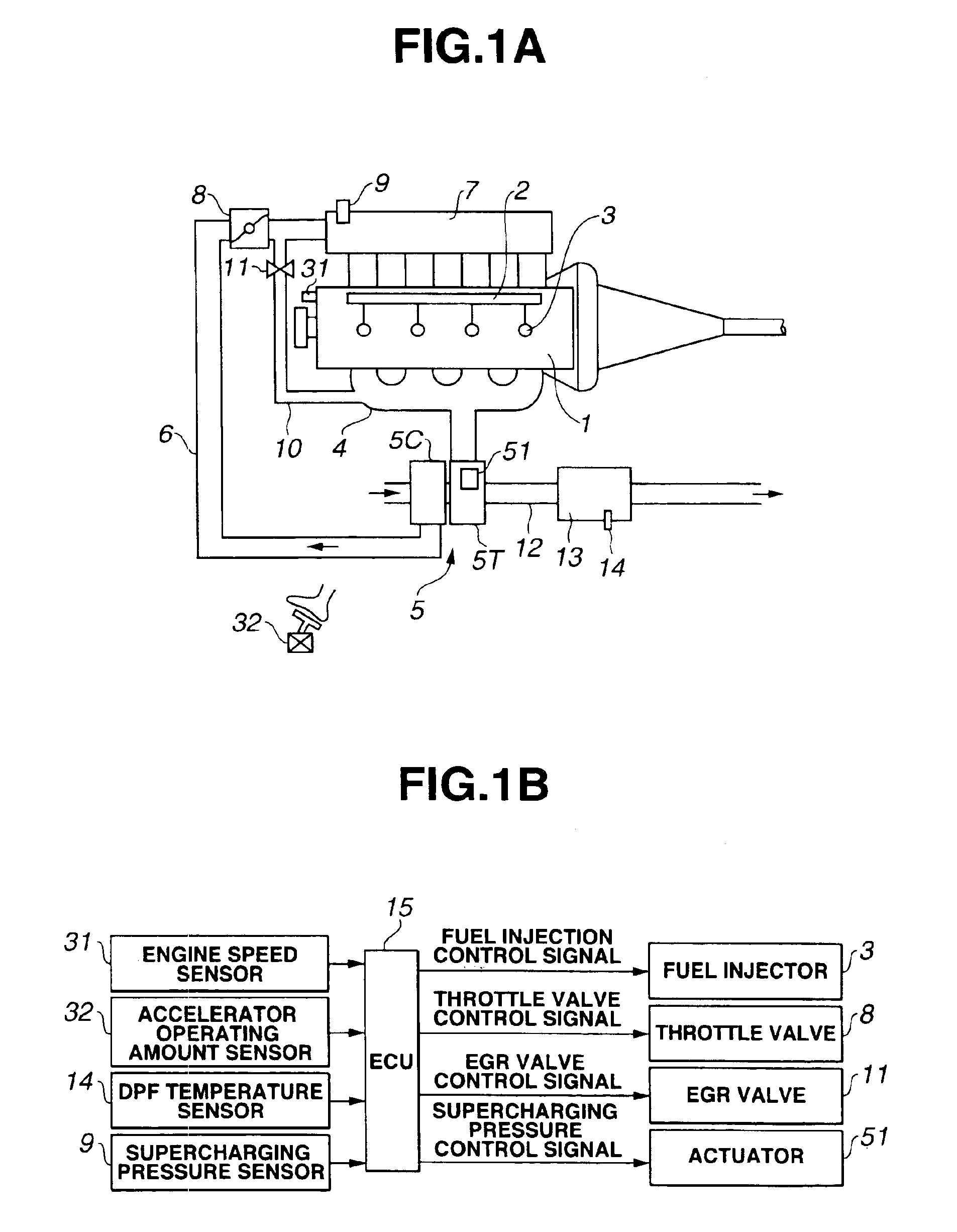
[0020]Referring now to FIG. 1A, an embodiment of an exhaust gas purifying system is illustrated in combination with an internal combustion engine 1 which is a diesel engine in this case. The engine 1 is provided with a common rail fuel injection system which includes a common rail 2 through which fuel is supplied to fuel injectors 3. Each fuel injector 3 has an electromagnetic valve which is switched ON to inject fuel and switched OFF to stop fuel injection. A fuel injection amount (the amount of fuel injected from fuel injector 3) of fuel injector 3 is determined by a fuel injection control signal fed to fuel injector 3. The common rail 2 is supplied with fuel from a fuel supply pump (not shown).

[0021]Engine 1 includes an exhaust manifold 4 through which exhaust gas from the cylinders of engine 1 flows. Turbocharger 5 includes a turbine 5T which is disposed downstream of exhaust manifold 4 so that exhaust gas from exhaust manifold 4 is supplied to turbine 5T. Compressor 5C of turbo...


PUM


Abstract

An exhaust gas purifying system for an automotive internal combustion engine. The exhaust gas purifying system includes a particulate filter disposed in an exhaust gas passageway of the engine to collect particulate in exhaust gas flowing through the exhaust gas passageway. The collected particulate is burnt off to be removed by raising a temperature of exhaust gas in a condition in connection with the particulate filter. A plurality of devices are provided for raising the temperature of exhaust gas to be introduced into the particulate filter through the exhaust gas passageway when the collected particulate is burned off to be removed. Additionally, a control unit is configured to select at least one of the devices in accordance with an engine operating region and preferentially operate the selected at least one of the devices for raising the exhaust gas temperature.

Description

BACKGROUND OF THE INVENTION[0001]This invention relates to improvements in an exhaust gas purifying system, and more particularly to a technique for burning off particulate (Particulate Matter in exhaust gas, referred hereafter to as “PM”) in exhaust gas collected in a filter, by raising the temperature of exhaust gas.[0002]In recent years, internal combustion engines, particularly diesel engines are equipped with a Diesel Particulate Filter (referred hereinafter to as “DPF”) for collecting PM in exhaust gas. When the amount of the collected PM reaches a certain level, the temperature of exhaust gas is raised to burn off PM thereby regenerating DPF, as disclosed in Japanese Patent Provisional Publication No. 2002-89327.SUMMARY OF THE INVENTION[0003]When the DPF is regenerated, a plurality of exhaust gas temperature raising means are used together in order to effectively raise the exhaust gas temperature. However, these means are different in temperature rising sensitivity and influe...

Claims


Application Information

Patent Timeline
Patent Type & Authority Patents(United States)
IPC IPC(8): F01N3/023F02D21/00F02D23/00F02D41/02F02D21/08F02D41/40F02B37/00F02M25/07F01N3/02F02B37/12F02B37/24F02D41/04F02D41/14F02D41/38F02D43/00F02D45/00
CPCF01N3/023F02D23/00F02D41/0055F02D41/024F02D41/029F02B37/00F02D41/0245F02D41/1446F02D41/405F02M25/0707F02M25/0713Y02T10/144Y02T10/26Y02T10/47F02M26/05F02M26/10Y02T10/12Y02T10/40
Inventor OTAKE, MAKOTOKAWASHIMA, JUNICHITSUTSUMOTO, NAOYAKONDOU, TERUNORIINOUE, TAKAOKOGA, TOSHIMASA
Owner NISSAN MOTOR CO LTD
Why Eureka
Try Eureka