Arrangement for coupling microwave energy into a treatment chamber

a technology for treating chambers and microwave energy, applied in the direction of resonators, using liquid separation agents, chemical vapor deposition coatings, etc., can solve the problems of no longer affording satisfactory, and achieve the effect of adequate level of efficiency, low reflection power, and moderate reflection factor drop in power

Inactive Publication Date: 2005-10-11
TETRA LAVAL HLDG & FINANCE SA
View PDF4 Cites 45 Cited by
  • Summary
  • Abstract
  • Description
  • Claims
  • Application Information

AI Technical Summary

Benefits of technology

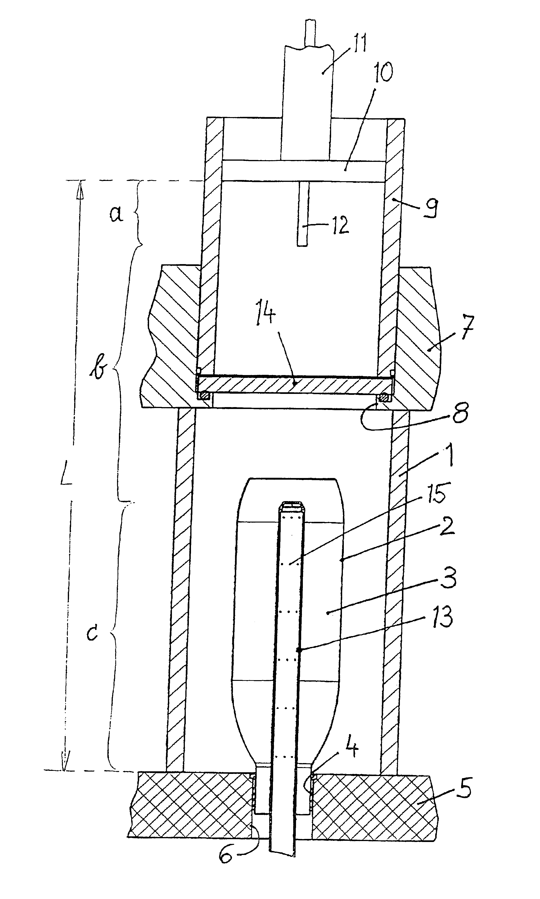
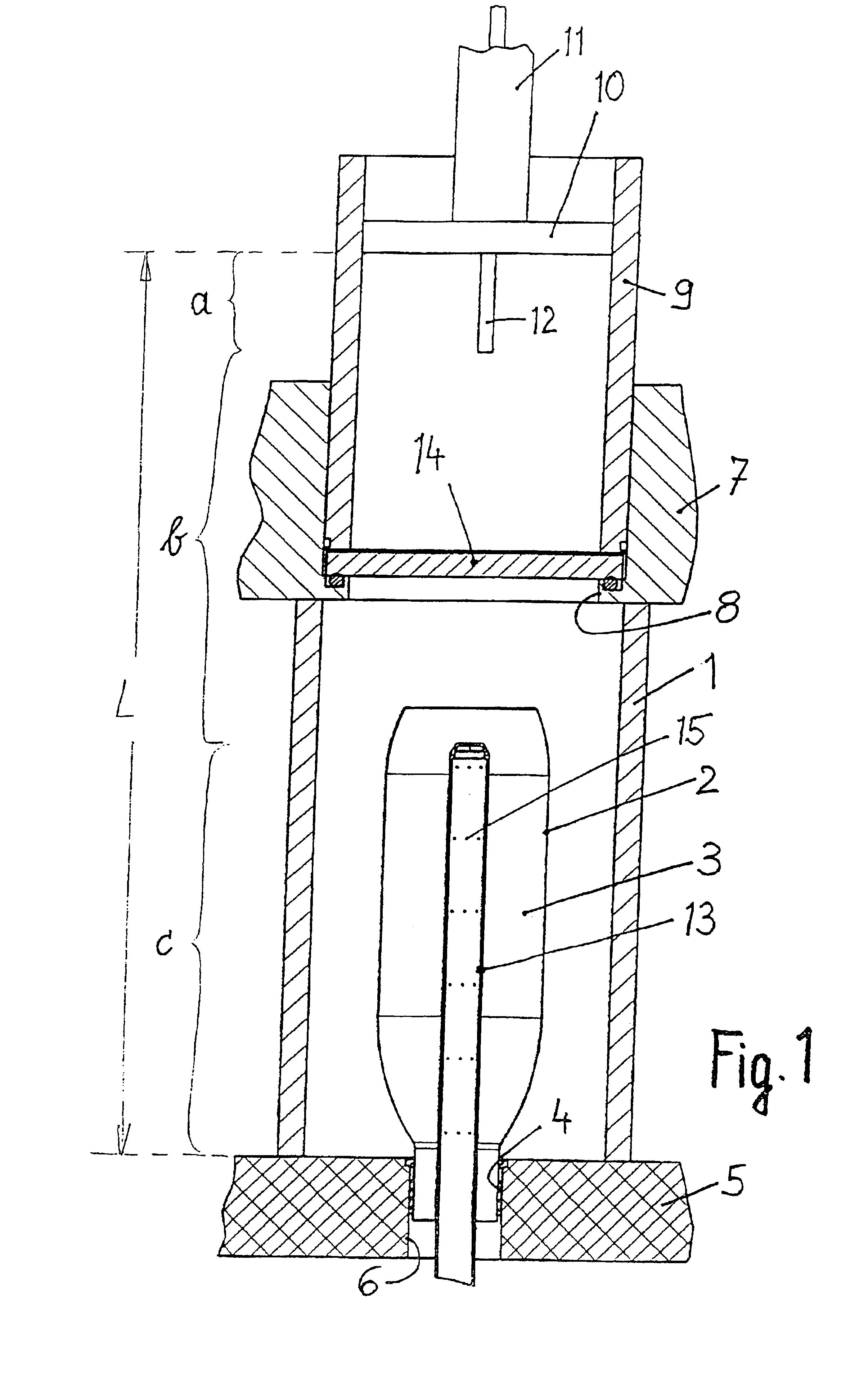
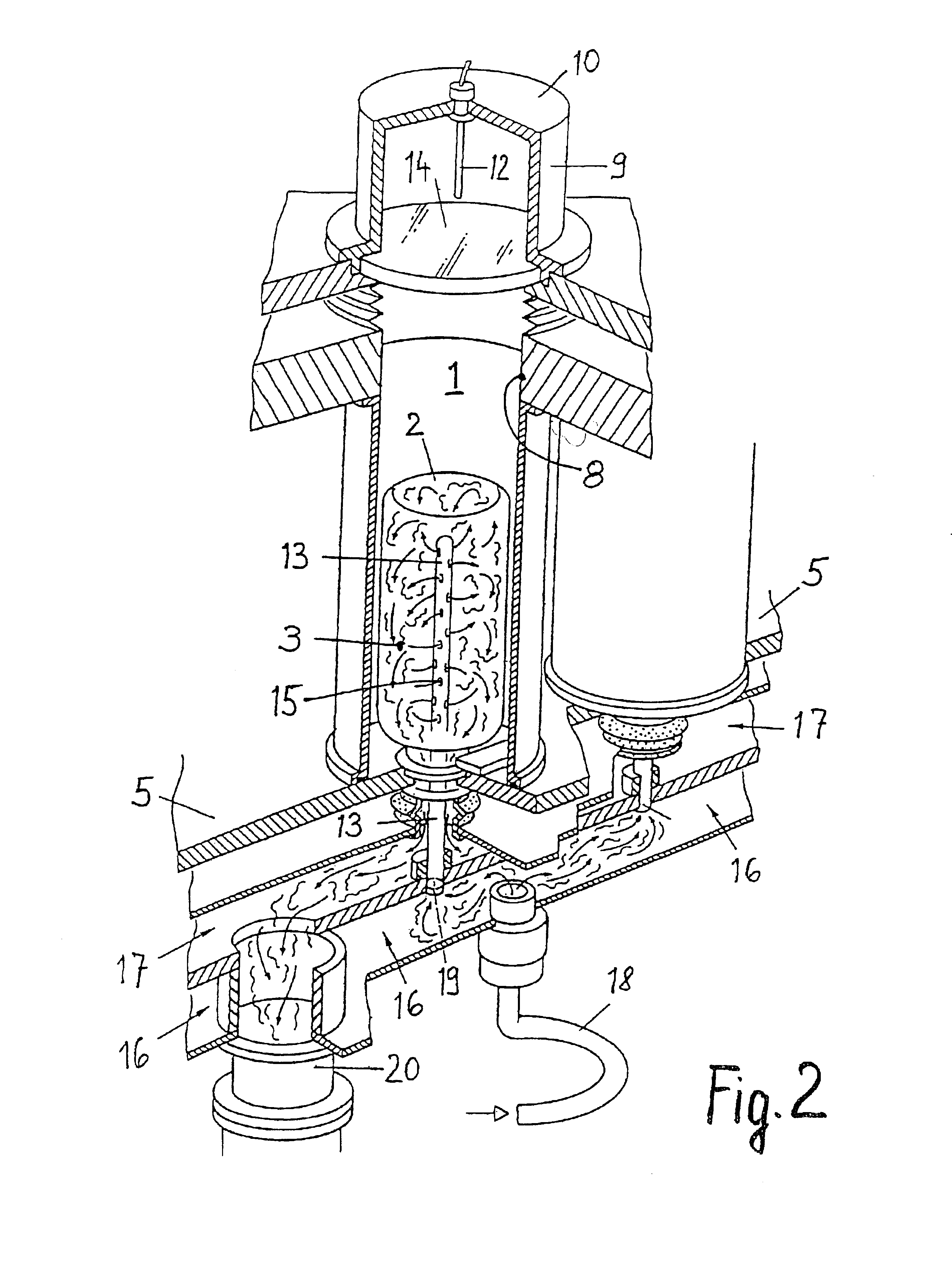
[0006]Surprisingly, in accordance with the invention the object stated is attained in that the arrangement is of a substantially cylindrical structure, such that provided at the rear end is a first coaxial waveguide with an internal conductor in the form of an antenna, an approximately cylindrical waveguide follows in the centre of the arrangement and provided at the front end is a second coaxial waveguide with internal conductor, wherein gas can be introduced through a gas feed tube into the second coaxial waveguide, which gas can be activated into the plasma state by the coupled-in microwave energy, and wherein a TM-mode is produced by the antenna in the plasma region. Those measures afford a somewhat more moderate reflection factor drop in power in dependence on the geometry of the container, with the consequence that even containers of unequal volumes and different configurations can nonetheless always still be effectively treated because sufficient microwave power is available for firing and maintaining the plasma, that is to say the reflected power is low. A need for complete fresh adaptation occurs only when the volume of the treated containers changes by a factor of two or more and in a corresponding fashion the configuration of the one container is also altered in a highly drastic manner with respect to the other. The measures according to the invention provide that different containers of similar shape and size can be treated with an adequate level of efficiency, without involving conversion work.
[0007]It is not only the substantially cylindrical form of the cavity resonator but also the avoidance of mismatching effects that contribute to the good treatment results and coupling-in of the microwave power with a good degree of efficiency also succeeds due to the successive arrangement of the three electrically different waveguide portions, wherein the first waveguide is a coaxial conductor, the second is a cylindrical waveguide (at the centre) and the front conductor is again a second coaxial waveguide. The great advantage of the arrangement of those three portions is also the possibility of separating or sealing off the one portion with respect to the other. In addition, the separation of those portions which differ in terms of function afforded a particular degree of effectiveness in regard to coupling in the microwave power.

Problems solved by technology

In addition it has been found that, depending on the respective size and configuration of the container to be coated, the losses and reflections of the coupled-in microwave energy differ to such an extent that, for a given configuration, it is necessary to implement an adaptation procedure which then no longer affords satisfactory results for the next, different configuration.

Method used


Image

  • Arrangement for coupling microwave energy into a treatment chamber
  • Arrangement for coupling microwave energy into a treatment chamber
  • Arrangement for coupling microwave energy into a treatment chamber

Examples


Embodiment Construction

[0012]It is particularly advantageous in accordance with the invention if the antenna of the first coaxial waveguide is of a bar shape and the length of the bar antenna is between 40 mm and 100 mm. With such a bar antenna (equally well as with the other embodiments of the antennae which are described hereinafter) it is possible to achieve a TM-mode, that is to say transverse magnetic field lines in the three portions of the arrangement, while the production of the TM-mode is possible in particular in the plasma region. The arrangement according to the invention also works well with a bar antenna whose length is between 50 and 60 mm. The bar antenna can be made from copper and can be about 8 mm in outside diameter. However outside diameters from the range of sizes of between 2 mm and 10 mm also function well.

[0013]It is further desirable in accordance with the invention if, in accordance with an alternative embodiment, the antenna of the first coaxial waveguide is in the form of a co...


PUM

PropertyMeasurementUnit
lengthaaaaaaaaaa
lengthaaaaaaaaaa
lengthaaaaaaaaaa

Abstract

An arrangement for coupling microwave energy into a plasma CVD coating chamber (3) disposed in a cavity resonator (1) has a microwave feed (11) and a microwave waveguide (9, 1). So that a plastic container of a size and configuration which differ to a certain degree can be effectively coated in its interior, it is provided that the arrangement is of a substantially cylindrical structure, such that provided at the rear end is a first coaxial waveguide (in the region a) with an internal conductor in the form of an antenna (12), an approximately cylindrical waveguide (in the region b) follows in the centre of the arrangement and provided at the front end (in the region c) is a second coaxial waveguide (1) with internal conductor (13), wherein gas can be introduced through a gas feed tube (13) into the second coaxial waveguide (in the region c), which gas can be activated into the plasma state by the coupled-in microwave energy, and wherein a TM-mode is produced by the antenna (12) in the plasma region (1, c).

Description

BACKGROUND OF THE INVENTION[0001]The invention concerns an arrangement for coupling microwave energy into a treatment chamber disposed in a cavity resonator, in particular a plasma CVD coating chamber, comprising a microwave feed and a microwave waveguide.[0002]Apparatuses are known for producing a plasma which serves for example for coating, cleaning, modifying and etching substrates, but also for treating medical implants. Workpieces of the most widely varying shapes are coated. Known apparatuses for producing plasma have an annular resonator to which microwaves are fed by way of a waveguide and a coaxial cable.[0003]The coating of motor vehicle tanks is also known, in which case four or more microwave sources in the form of magnetrons are arranged in the outside wall of the cavity resonator, in order to activate a gas which has been previously introduced into the tank, to the plasma state, by means of the coupled-in microwave energy. At least four magnetrons are required for a ta...

Claims


Application Information

Patent Timeline
Patent Type & Authority Patents(United States)
IPC IPC(8): H01J37/32C23C16/511H01P7/06
CPCH01J37/32192H01J37/3222H01J37/3244H01J37/32532
Inventor MOORE, RODNEYESSERS, WOLF
Owner TETRA LAVAL HLDG & FINANCE SA
Why Eureka
Try Eureka