Biological data observation apparatus

a technology of biological data and measuring apparatus, applied in the field of biological data measuring apparatus, can solve problems such as inflicting pain on patients, and achieve the effect of simplifying the measurement procedur

Inactive Publication Date: 2005-10-11
KABUSHIKI GAISYA K AND S
View PDF24 Cites 116 Cited by
  • Summary
  • Abstract
  • Description
  • Claims
  • Application Information

AI Technical Summary

Benefits of technology

[0007]Therefore, an object of the present invention is to provide a biological data observation apparatus which can calculate a blood pressure value without the preparatory measurement with the cuff.
[0009]According to the above-described biological data observation apparatus, the storage area stores the blood pressure conversion data in which the pulse-wave area of the photoelectric volume pulse-wave and blood pressure value are correlated with each other. Accordingly, when a photo electric volume pulse wave of the subject is measured by the photoelectric sensor, a blood pressure value of the subject is obtained from the pulse wave area of the photoelectric volume pulse wave and the blood pressure conversion data. Consequently, the above-described apparatus can eliminate the measurement of pressure pulse wave by a cuff in the initial stage of measurement and resultant calibration, whereupon the measuring procedure can be simplified.

Problems solved by technology

However, several times of pressure application against an artery of the subject inflict pain on him or her when the measurement with the cuff is done over again.

Method used


Image

  • Biological data observation apparatus
  • Biological data observation apparatus
  • Biological data observation apparatus

Examples


first embodiment

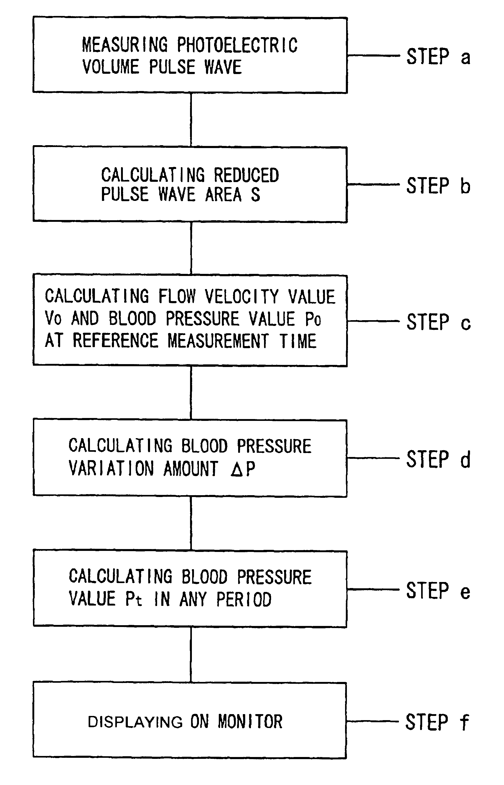
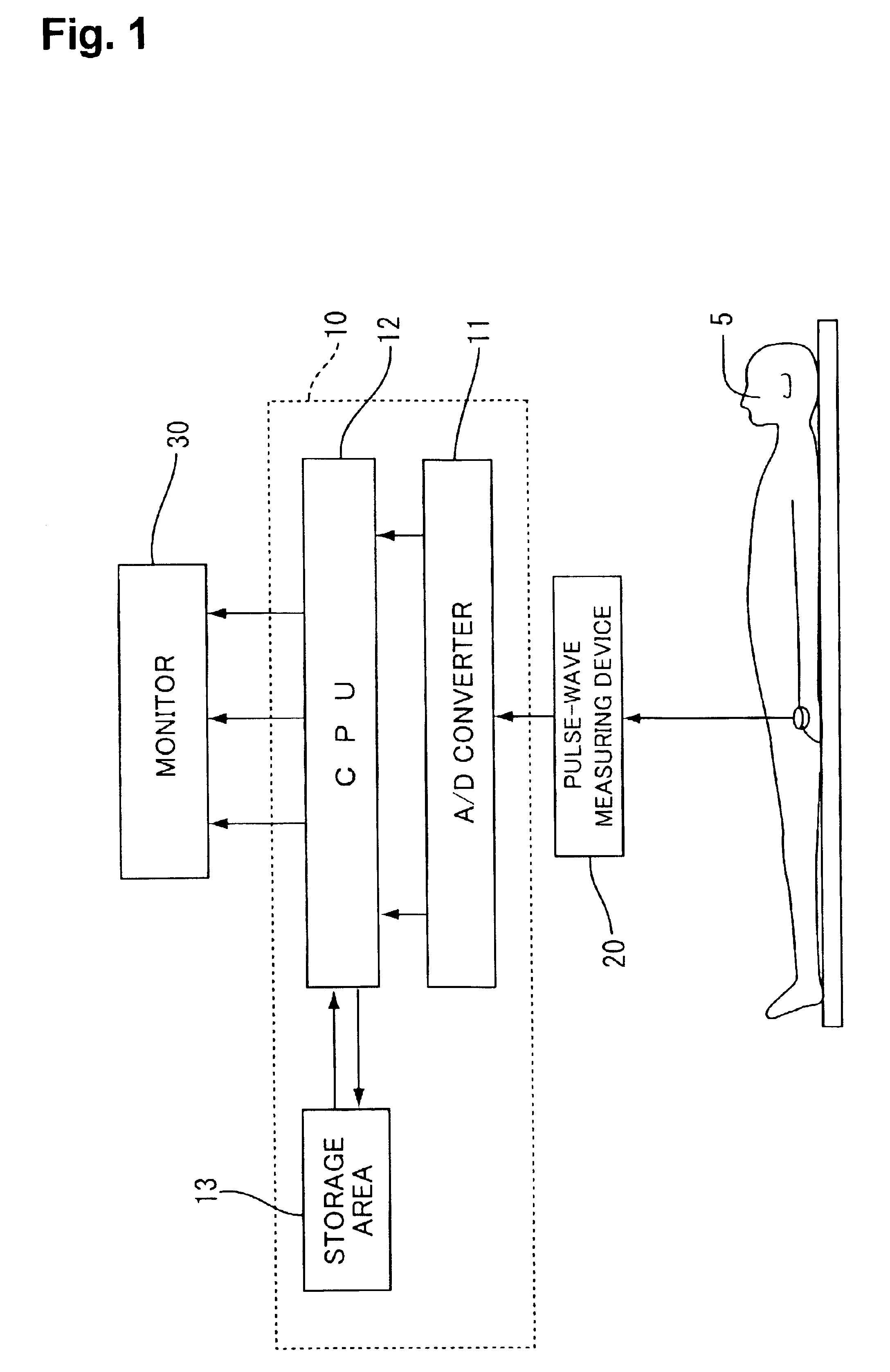
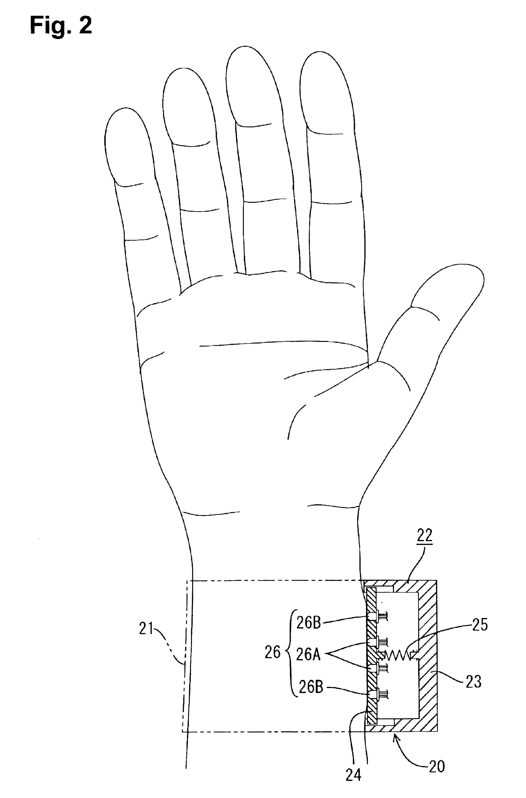
[0037]A first embodiment of the present invention will be described with reference to FIGS. 1 to 7. Referring to FIG. 1, a biological data observation apparatus in accordance with the invention is shown. The biological data observation apparatus comprises a pulse-wave measuring device 20, a data processing device 10 connected to an output line of the pulse-wave measuring device 20 to carry out operational processing, and a monitor 30 (serving as a display unit in the invention) displaying results of operational processing by the data processing device 10. The pulse-wave measuring device 20 includes a photoelectric sensor 6 (serving as a measuring unit in the invention) irradiating light with a predetermined wavelength onto a blood vessel of a subject 5 thereby to detect, as a photoelectric volume pulse wave, a change in amount of resultant transmitted or reflected light.

[0038]The data processing device 10 includes an A / D converter 11, a CPU 12 (serving as an operational unit in the ...

third embodiment

[0070]Determination of the photoelectric volume pulse wave by the data processing device 10 will now be described with reference to FIG. 11. In the third embodiment, the determination of the photoelectric volume pulse wave depends upon whether a period of the photoelectric volume pulse wave is within a predetermined allowed range (step j). The predetermined allowed range is a normal range of the period of the photoelectric volume pulse wave, for example, a range of 0.75 to 1.5 sec. When a large body motion occurs, in the subject 5 during measurement of a photoelectric volume pulse wave, the waveform of the photoelectric volume pulse wave is disturbed such that the period thereof is Out of the allowed range. When determining that the period of the photoelectric volume pulse wave is within the allowed range, the data processing device 10 advances to a first blood pressure calculating step (step k), whereas the data processing device 10 advances to a step in which the substitution of t...

fourth embodiment

[0084]In the fourth embodiment, a plurality of primary biological data closely related with a degree of anesthesia are put together into a signal data for the purpose of measuring the anesthesia depth. Accordingly, since a plurality of primary biological data are compensated by one another, a more accurate anesthetic depth T can be obtained as compared with the case where the anesthetic depth is calculated on the basis of a single primary biological data.

[0085]The calculated composite data A is stored in the storage area 13. Even if measurement of the primary biological data about the subject 5 starts after application of anesthesia, the anesthetic depth T can be calculated. More specifically, the data processing device 10 collates a change pattern (transition from start of measurement to stabilization of composite data) of composite data B calculated on the basis of the primary biological data with change patterns of accumulated previous composite data, thereby extracting similar c...


PUM


Abstract

A biological data observation apparatus includes a measuring unit including at least a photoelectric sensor including a light emitting element for emitting light with a predetermined wavelength onto a blood vessel of a subject and a light detecting element for detecting, as a photoelectric volume pulse wave, a change in an amount of transmitted or reflected light resulting from the light emitted from the light emitting section, a storage area in which pressure conversion data correlating a pulse wave area and a blood pressure value in order that the pulse wave area may be converted to the blood pressure value as an absolute value, the pulse wave area being obtained by integrating a wave form of the photoelectric capacity pulse wave per heartbeat, an operational unit calculating the pulse wave area on the basis of the photoelectric volume pulse wave obtained from the subject and further calculating the blood pressure value of the subject on the basis of the calculated pulse wave area and the blood pressure conversion data, and a display unit displaying a result of calculation performed by the operational unit.

Description

INCORPORATION BY REFERENCE[0001]This application is based on Japanese Patent Application No. 2001-375925 filed on Dec. 10, 2001, No. 2001-377083 filed on Dec. 11, 2001, No. 2002-000856 filed on Jan. 07, 2002, No. 2002-113656 filed on Apr. 16, 2002, and No. 2002-316337 filed on Oct. 30, 2002, the content of which is incorporated hereinto by reference.BACKGROUND OF THE INVENTION[0002]1. Field of the Invention[0003]This invention relates to a biological data measuring apparatus which measures biological data such as blood pressure, pulses, etc.[0004]2. Description of the Related Art[0005]In one conventional method of continuously measuring blood pressure values, a cuff is used to measure a blood pressure value of a subject at an initial stage of measurement and thereafter, a blood pressure value is calculated on the basis of transition of a photoelectric volume pulse wave obtained from a photoelectric sensor. Thus, both the cuff and the photoelectric sensor are commonly used at the ini...

Claims


Application Information

Patent Timeline
Patent Type & Authority Patents(United States)
IPC IPC(8): A61B5/021A61B5/026A61B5/0285A61B5/00
CPCA61B5/021A61B5/0285A61B5/4266A61B5/4821A61B5/02108
Inventor KONDO, SHINJISAKAKIBARA, NORIAKITAKEMOTO, TORUHONDA, TOSHIHIRO
Owner KABUSHIKI GAISYA K AND S
Why Eureka
Try Eureka