CT detector fabrication process

a fabrication process and detector technology, applied in the field of diagnostic imaging, can solve the problems of not being a viable diagnostic imaging tool, ct imaging would not provide data or feedback as to the number and/or energy of photons detected, and ct imaging would not provide energy discriminatory data or other ways to count the number and/or energy of photons actually received by a given detector element or pixel, so as to reduce the effect of beam hardening and better visualization

Active Publication Date: 2005-10-11
GENERAL ELECTRIC CO
View PDF7 Cites 73 Cited by
  • Summary
  • Abstract
  • Description
  • Claims
  • Application Information

AI Technical Summary

Benefits of technology

[0010]The CT detector supports not only x-ray photon counting, but energy measurement or tagging as well. As a result, the present invention supports the acquisition of both anatomical detail as well as tissue characterization information. In this regard, the energy discriminatory information or data may be used to reduce the effects of beam hardening and the like. Further, these detectors support the acquisition of tissue discriminatory data and therefore provide diagnostic information that is indicative of disease or other pathologies. For example, detection of calcium in a plaque in a view is possible. This detector can also be used to detect, measure, and characterize materials that may be injected into a subject such as contrast agents and other specialized materials such as targeting agents. Contrast materials can, for example, include iodine that is injected into the blood stream for better visualization. A method of fabricating such a detector is also disclosed.

Problems solved by technology

A drawback of such detectors is their inability to provide data or feedback as to the number and / or energy of photons detected.
While it is generally recognized that CT imaging would not be a viable diagnostic imaging tool without the advancements achieved with conventional CT detector design, a drawback of these detectors is their inability to provide energy discriminatory data or otherwise count the number and / or measure the energy of photons actually received by a given detector element or pixel.
A drawback of direct conversion semiconductor detectors, however, is that these types of detectors cannot count at the very high x-ray photon flux rates typically encountered with conventional CT systems.
What can be problematic, however, is that the bowtie filter may not be optimum given that a subject population is significantly less than uniform and not exactly elliptical in shape.
Low x-ray flux in the projection will ultimately contribute to noise in the reconstructed image of the subject.
However, this solution leads to increased scanned time.
That is, there is a penalty that the acquisition time for the image is increased in proportion to the nominal flux needed to acquire a certain number of x-rays that meet image quality requirements.
However, these algorithms may imperfectly replace the saturated data as well as contribute to the complexity of the CT system.

Method used


Image

  • CT detector fabrication process
  • CT detector fabrication process
  • CT detector fabrication process

Examples


Embodiment Construction

[0027]The operating environment of the present invention is described with respect to a four-slice computed tomography (CT) system. However, it will be appreciated by those skilled in the art that the present invention is equally applicable for use with single-slice or other multi-slice configurations. Moreover, the present invention will be described with respect to the detection and conversion of x-rays. However, one skilled in the art will further appreciate that the present invention is equally applicable for the detection and conversion of other radiographic energy.

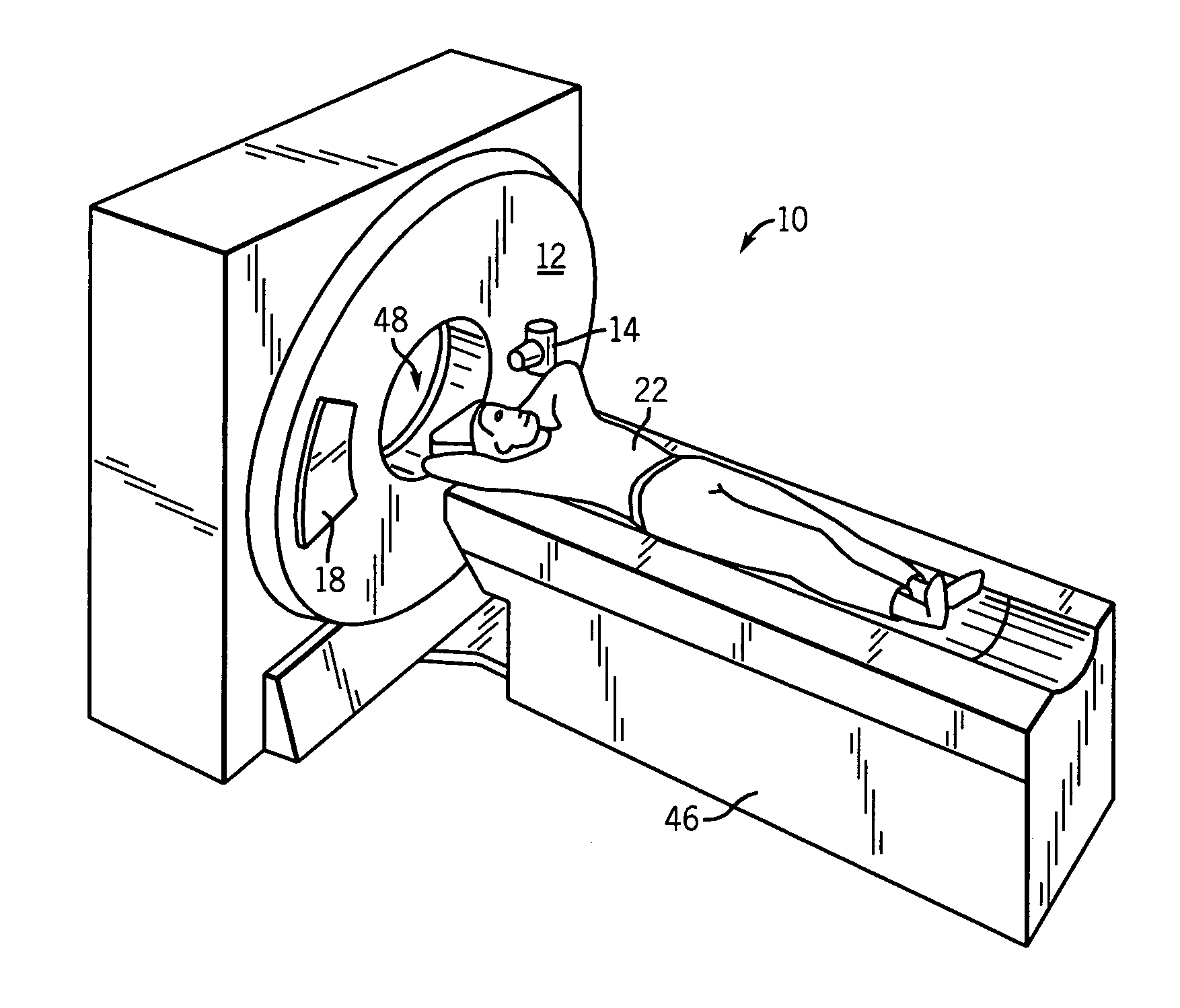
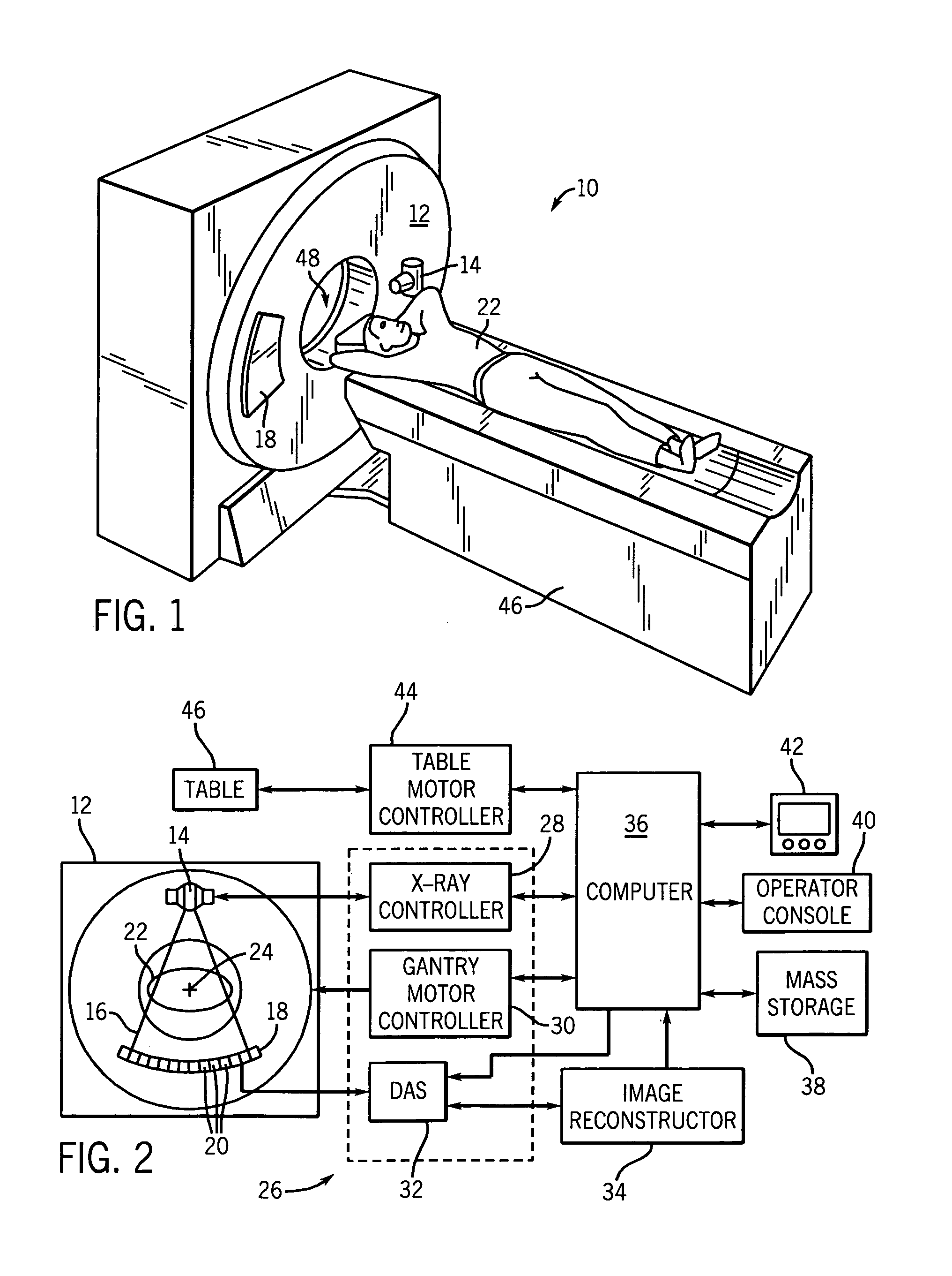
[0028]Referring to FIGS. 1 and 2, a computed tomography (CT) imaging system 10 is shown as including a gantry 12 representative of a “third generation” CT scanner. Gantry 12 has an x-ray source 14 that projects a beam of x-rays 16 toward a detector assembly 18 on the opposite side of the gantry 12. Detector assembly 18 is formed by a plurality of detectors 20 which together sense the projected x-rays that pass throug...


PUM


Abstract

A CT detector capable of energy discrimination and direct conversion is disclosed. The detector includes multiple layers of semiconductor material with the layers having varying thicknesses. The detector is constructed to be segmented in the x-ray penetration direction so as to optimize count rate performance as well as avoid saturation.

Description

BACKGROUND OF THE INVENTION[0001]The present invention relates generally to diagnostic imaging and, more particularly, to a method of constructing and otherwise fabricating a direct conversion CT detector capable of providing photon count and / or energy data.[0002]Typically, in radiographic imaging systems, an x-ray source emits x-rays toward a subject or object, such as a patient or a piece of luggage. Hereinafter, the terms “subject” and “object” may be interchangeably used to describe anything capable of being imaged. The beam, after being attenuated by the subject, impinges upon an array of radiation detectors. The intensity of the attenuated beam radiation received at the detector array is typically dependent upon the attenuation of the x-rays. Each detector element of the detector array produces a separate electrical signal indicative of the attenuated beam received by each detector element. The electrical signals are transmitted to a data processing system for analysis which u...

Claims


Application Information

Patent Timeline
Patent Type & Authority Patents(United States)
IPC IPC(8): A61B6/03G01J1/10G01J1/24G01T1/24G01T1/29G01T1/00G21K4/00H01L31/18H01L31/0264H01L31/0296H01L31/115
CPCG01T1/242G01T1/249
Inventor HOFFMAN, DAVID M.
Owner GENERAL ELECTRIC CO
Why Eureka
Try Eureka