Color filter substrate, method for manufacturing the same, liquid crystal display panel, and electronic equipment

a technology of color filter substrate and liquid crystal display panel, which is applied in the direction of mirrors, optics, instruments, etc., can solve the problems of reducing the and the shortage of chroma of the transmissive display becomes more remarkable, so as to achieve the effect of further improving the light-shielding property

Inactive Publication Date: 2005-10-11
138 EAST LCD ADVANCEMENTS LTD
View PDF11 Cites 9 Cited by
  • Summary
  • Abstract
  • Description
  • Claims
  • Application Information

AI Technical Summary

Benefits of technology

[0009]According to this color filter substrate, since the light, which reaches the surface of the reflection layer and which is reflected at the surface, passes through the light-color portion having a low optical density, the brightness of the reflected light can be maintained at a high level. On the other hand, since the light, which has passed through the translucent portion of the reflection layer, passes through the deep-color portion having a high optical density, the chroma of the transmitted light can be maintained at a high level. Furthermore, since the light-shielding layer is composed of a laminate of the deep-color portions having a high optical density in the color filters, an excellent light-shielding property can be achieved.
[0020]In these methods for manufacture, when the aforementioned deep-color portion and light-color portion are formed, it is desirable to form the light-shielding layer composed of a laminate of the deep-color portions of the aforementioned plurality of color filters and the light-color portion of at least one color filter of the aforementioned plurality of color filters. According to this, the light-shielding property can be further improved compared with that of the light-shielding layer composed of only deep-color portions of the color filters.

Problems solved by technology

Consequently, there has been a problem in that the chroma in the transmissive display has become lower than the chroma in the reflective display.
However, in such a case, the shortage of chroma in the transmissive display becomes more remarkable.

Method used


Image

  • Color filter substrate, method for manufacturing the same, liquid crystal display panel, and electronic equipment
  • Color filter substrate, method for manufacturing the same, liquid crystal display panel, and electronic equipment
  • Color filter substrate, method for manufacturing the same, liquid crystal display panel, and electronic equipment

Examples


first embodiment

A. First Embodiment

[0034]The first embodiment will be described, in which the present invention is applied to a semitransparent reflective liquid crystal display panel of an active matrix system. In the case exemplified below, a TFD (Thin Film Diode) element, which is a two-terminal switching element, is used as a switching element.

A-1: Configuration of Liquid Crystal Display Panel

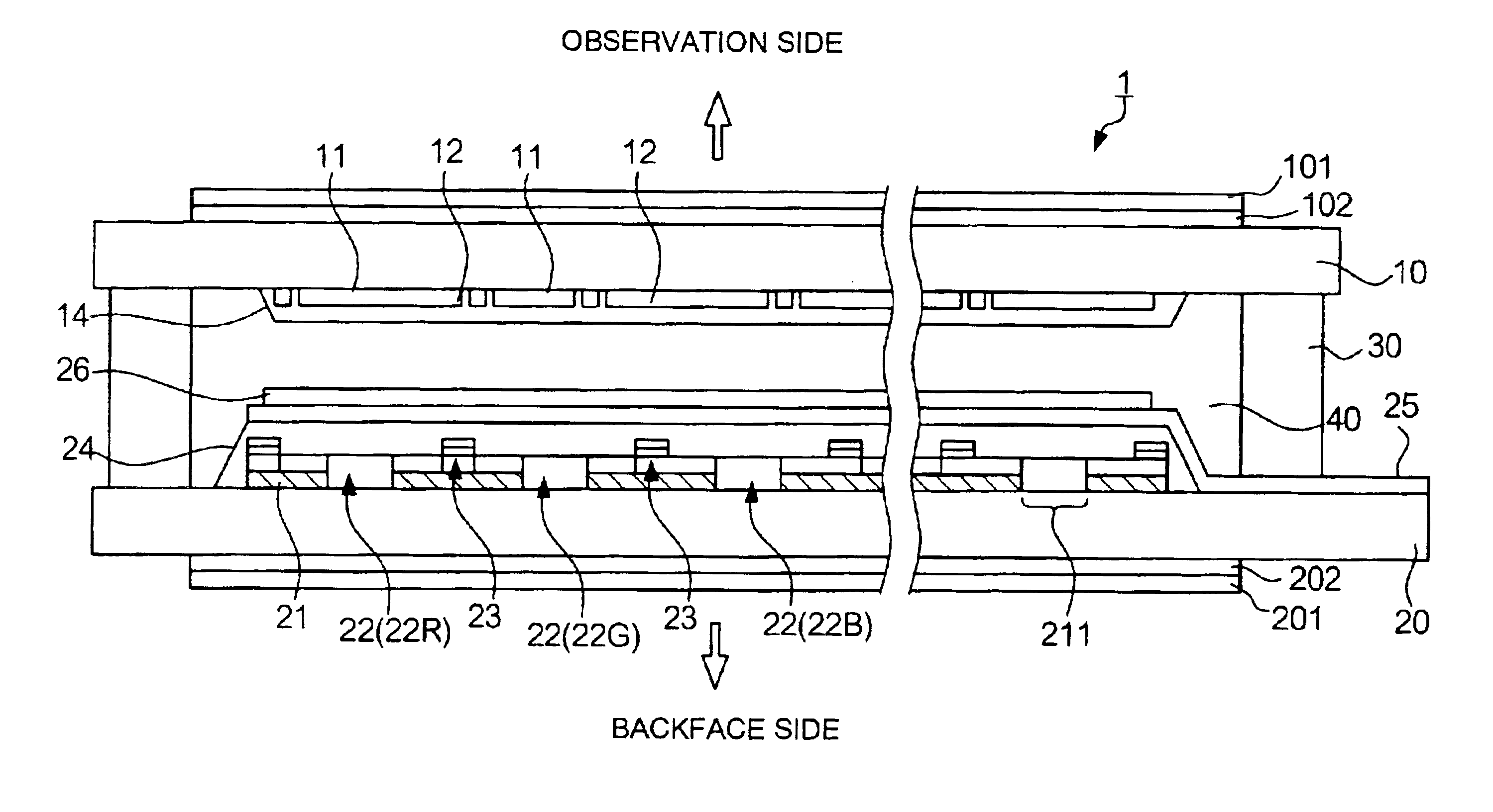
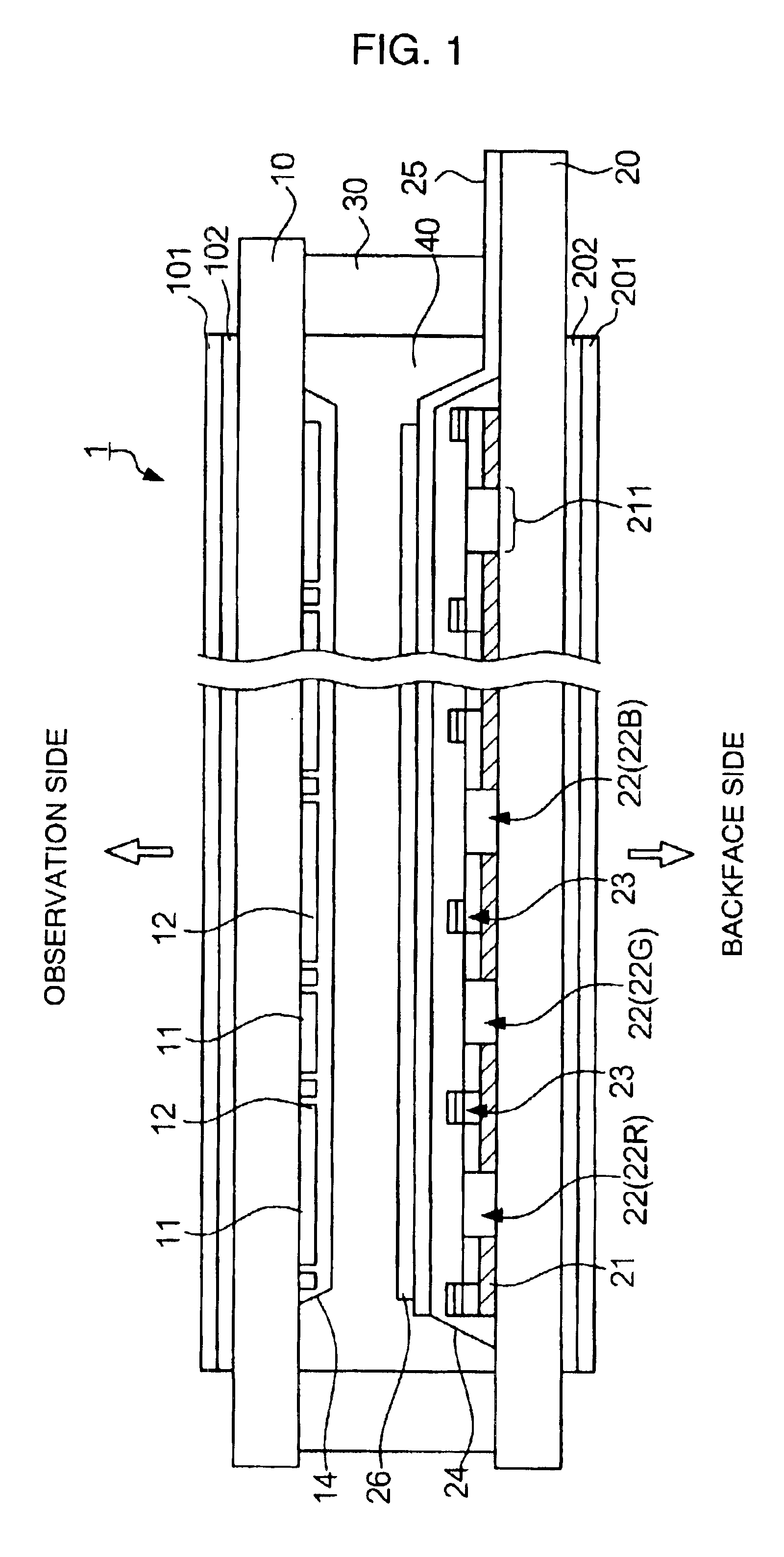
[0035]FIG. 1 is a sectional view showing the configuration of a liquid crystal display panel according to the present embodiment. As shown in FIG. 1, this liquid crystal display panel 1 has a configuration in which a first substrate 10 and a second substrate 20 facing each other are adhered with a sealing member 30 therebetween and, in addition, a liquid crystal 40 of, for example, TN (Twisted Nematic) type and STN (Super Twisted Nematic) type, is encapsulated in the region surrounded by both of the substrates and the sealing member 30. Hereafter, the first substrate 10 side, when viewed from the liquid cr...

second embodiment

[0064]Next, the configuration of a liquid crystal display panel according to the second embodiment of the present invention will be described with reference to FIG. 7. Among the constituents shown in FIG. 7, common constituents with the liquid crystal display panel according to the first embodiment shown in the aforementioned FIG. 1 are indicated by the same reference numerals.

[0065]In the aforementioned embodiment, the configuration in which the color filters 22 and the light-shielding layer 23 are arranged on the surface of the second substrate 20 located on the backface side was exemplified. On the other hand, in a liquid crystal display panel 2 according to the present embodiment, as shown in FIG. 7, the color filters 22, the light-shielding layer 23, and the overcoat layer 24 are arranged on the surface of the first substrate 10 located on the observation side.

[0066]That is, the color filters 22 (22R, 22G, and 22B), each being colored any one of red, green, and blue, are arrang...

modified example

[0069]The aforementioned embodiments are no more than an exemplification, and various modifications can be applied to the aforementioned embodiments within the purport of the present invention. It is considered that modified examples include, for example, the following.


PUM

PropertyMeasurementUnit
optical densityaaaaaaaaaa
wavelengthsaaaaaaaaaa
optical densityaaaaaaaaaa

Abstract

Each color filter 22 includes a deep-color portion 221 being superimposed on a translucent portion 211 of a reflection layer 21 and a light-color portion 222 having an optical density lower than that of the deep-color portion 221. A light-shielding layer 23 for shielding the gaps between individual subpixels 7 from light is a laminate composed of at least a deep-color portion 221B of a blue color filter 22B, a deep-color portion 221R of a red color filter 22R, and a deep-color portion 221G of a green color filter 22G.

Description

DETAILED DESCRIPTION OF THE INVENTION[0001]1. Technical Field of the Invention[0002]The present invention relates to a color filter substrate and a method for manufacturing the same, and a liquid crystal display panel and electronic equipment using the color filter substrate.[0003]2. Description of the Related Art[0004]Conventionally, so-called semitransparent reflective liquid crystal display panels, in which the reflective display and the transmissive display can be changed on an as needed basis, have been suggested. As shown in FIG. 12, in this sort of liquid crystal display panel, a reflection layer 21 including a translucent portion 211 (opening) is arranged on a second substrate 20 facing a first substrate 10 so as to hold a liquid crystal 40 therebetween. On the observation side when viewed from the reflection layer 21, color filters 22, each being colored, for example, any one of red, green, and blue, are arranged. In FIG. 12, electrodes for applying a voltage to the liquid ...

Claims


Application Information

Patent Timeline
Patent Type & Authority Patents(United States)
IPC IPC(8): G02F1/1335G02F1/13G02B5/00G02B5/02G02B5/08G02B5/20G02F1/1333
CPCG02F1/133512G02F1/133514G02F1/133555G02F1/136227G02F1/1365G02F1/1335
Inventor TAKIZAWA, KEIJIOTAGIRI, YOSHIHIRONAKANO, TOMOYUKI
Owner 138 EAST LCD ADVANCEMENTS LTD
Why Eureka
Try Eureka