Light source apparatus and projector

a technology of light source apparatus and projector, which is applied in the direction of lighting and heating apparatus, instruments, and spectral modifiers, can solve the problems of small amount of heat transfer from the rotating disk to the air, decrease in the conversion efficiency of the yag phosphor itself, and shorten the irradiation period at a single point, so as to reduce the optical density of the excitation light on the wavelength conversion element, the effect of suppressing the increase in the temperature of the excitation section

Active Publication Date: 2018-05-08
SEIKO EPSON CORP
View PDF17 Cites 2 Cited by
  • Summary
  • Abstract
  • Description
  • Claims
  • Application Information

AI Technical Summary

Benefits of technology

[0020]Setting the shape of the spot of the excitation light with which the wavelength conversion element is irradiated to be long in the radial direction of the rotating disk but short in the circumferential direction thereof increases the area of a region irradiated with the excitation light per rotation of the rotating disk. Further, the irradiation period spent at a single point is shortened. As a result, the optical density of the excitation light on the wavelength conversion element decreases as compared with the optical density in related art, whereby an increase in the temperature of an excitation section can be suppressed. For example, the increase in the temperature in a case where the width of the excitation section is 2 mm is about 60% of the increase in the temperature in a case where the width of the excitation section is 1 mm, whereby the conversion efficiency of the wavelength conversion element and the reliability thereof increase. On the other hand, the wavelength conversion efficiency in a case where after the wavelength conversion element is excited but before it returns to the ground state, the wavelength conversion element is excited again is lower than the wavelength conversion efficiency in a case where the wavelength conversion element is excited from the ground state, but the proportion of the excitation in the low wavelength conversion efficiency state can be lowered, whereby a high wavelength conversion efficiency state, that is, bright light emission is achieved.

Problems solved by technology

In this process, at the time of the wavelength conversion, in which the blue light is converted into the yellow light, energy loss (Stokes loss) occurs, resulting in heat generation.
The heat dissipation is therefore insufficient, and the silicone resin is degraded due to high temperatures, resulting in a decrease in the conversion efficiency of the YAG phosphor itself.
It is, of course, conceivable to increase the number of revolutions of the rotating disk and the radius thereof, but countermeasures against the heat are still required in consideration of the facts that the amount of heat transfer from the rotating disk to the air is small and rotation power of a motor is limited.
Further, the heatproof temperature of quantum dots is about 100° C., which means that it is impossible, from the viewpoint of reliability, to irradiate quantum dots with high-energy excitation light in a small spot.

Method used


Image

  • Light source apparatus and projector
  • Light source apparatus and projector
  • Light source apparatus and projector

Examples


first embodiment

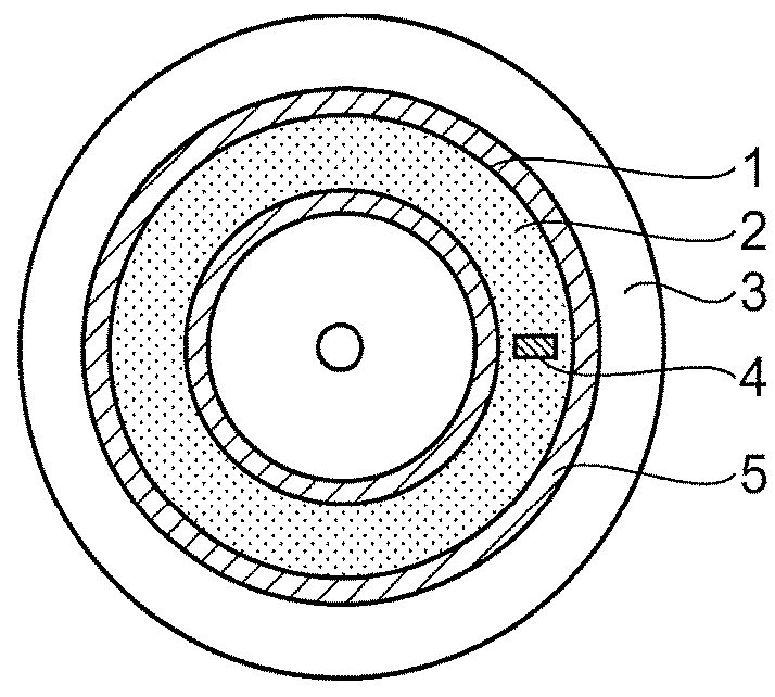
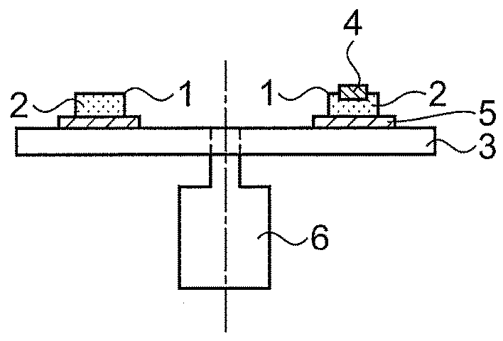
[0033]FIG. 1 is a plan view and a cross-sectional view of a rotating light emitting device in a light source apparatus according to a first embodiment. The rotating light emitting device includes a wavelength conversion element 1, a rotating disk 3, and a reflection film 5. The wavelength conversion element 1 is made of a silicone resin in which a plurality of particles that form a YAG phosphor 2 are dispersed. The wavelength conversion element 1 is irradiated with excitation light. In the specification, a spot of the excitation light on the wavelength conversion element 1 is called an excitation section.

[0034]The wavelength conversion element 1 is provided on the upper surface of the rotating disk 3, which is made of aluminum and has a diameter of about 50 mm, and has a donut-like shape having a thickness of 0.2 mm and a width of 5 mm. The rotating disk 3 is thick enough to transfer heat in the wavelength conversion element 1 to the interior of the rotating disk 3 and dissipate the...

second embodiment

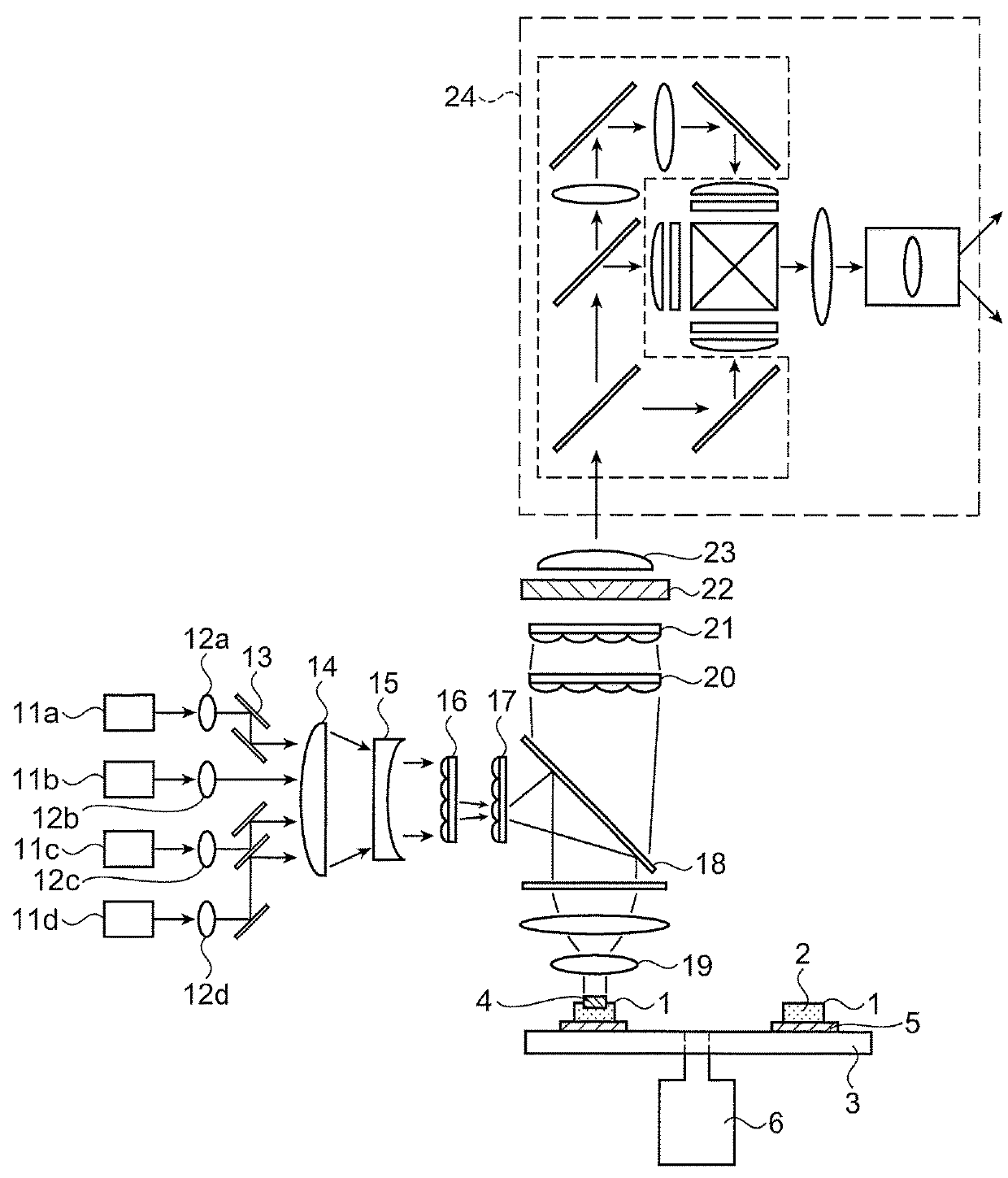
[0040]FIG. 2 shows, as a second embodiment, an optical system for achieving the shape of the excitation section 4 in the first embodiment and shows an optical system of a projector.

[0041]The projector in the present embodiment includes the light source apparatus in the first embodiment.

[0042]Blue light emitted from each of lasers 11a, 11b, 11c, and 11d is parallelized by collimator lenses 12a, 12b, 12c, and 12d, deflected by folding mirrors 13 so that the optical paths are effectively shortened, and converted by a collector lens 14 and a parallelizing lens 15 into spatially dense, parallelized light.

[0043]A lens array 16 is an array formed of individual lenses each of which has a shape similar to the shape of the excitation section 4, and a lens array 17 has the same number of individual lenses as the number of lenses in the lens array 16. The lens arrays 16 and 17 form an optical integration system. That is, laser rays having passed through the individual lenses in the lens array 1...

third embodiment

[0051]FIG. 7 is a plan view and a cross-sectional view of a rotating light emitting device provided in a light source apparatus according to a third embodiment. The rotating light emitting device in the present embodiment includes a YAG phosphor ceramic 61 as the wavelength conversion element, a rotating disk 62, and an adhesive 64, and an excitation section 63 is formed in the YAG phosphor ceramic 61. The YAG phosphor ceramic 61 is a YAG transparent crystal containing a trace amount of Ce ions. The thus formed YAG phosphor ceramic 61 is caused to adhere onto the rotating disk 62 with the adhesive 64. A highly reflective surface, such as an aluminum enhanced reflection film, is provided on the upper surface of the rotating disk 62 and reflects the yellow light produced in the YAG phosphor ceramic 61. To this end, the adhesive 64 is made of a transparent resin. In consideration of the thermal conductivity of the adhesive 64, the thickness thereof is desirably on the order of microns....


PUM


Abstract

A light source apparatus includes a light source that outputs excitation light, and a rotating light emitting device in which a wavelength conversion element that emits light when irradiated with the excitation light is provided on a rotating disk. A spot of the excitation light on the wavelength conversion element has a shape that is long in a radial direction of the rotating disk and short in a circumferential direction of the rotating disk. Alternatively, an orthogonally projected length of the spot in the radial direction is greater than an orthogonally projected length of the spot in the circumferential direction.

Description

BACKGROUND[0001]1. Technical Field[0002]The present invention relates to a light source apparatus and a projector.[0003]2. Related Art[0004]Using a solid-state light source as a light source of a liquid crystal projector on a commercial basis is underway (see JP-A-2012-47996). Blue light from a laser or any other solid-state light source is caused to impinge on a phosphor adhering to a rotating disk so as to cause the phosphor to emit yellow light. The yellow light can be combined with blue light from another laser to form white light. Light valves formed of three liquid crystal panels produce video images of three colors, which are combined with one another by a prism, and the combined video images are projected through a projection lens on a screen. A solid-state light source is characterized by a long period during which brightness is maintained, significantly low probability of blowout, and environmental friendliness owing to no mercury content as compared with a mercury lamp of...

Claims


Application Information

Patent Timeline
Patent Type & Authority Patents(United States)
IPC IPC(8): G03B21/20F21V9/40
CPCG03B21/208G03B21/204
Inventor HASHIZUME, TOSHIAKI
Owner SEIKO EPSON CORP
Why Eureka
Try Eureka