Expanding single mode fiber mode field for high power applications by fusion with multimode fiber

a multi-mode fiber and high-power technology, applied in the field of optical fibers, can solve the problems of inability to reliably operate at inability to design for such high optical intensities, and limitations in lens and lens performance choice, so as to reduce the light intensities at the fiber tip, reduce the loss of high-power coupling of optical fibers, and reduce the effect of light intensity

Active Publication Date: 2007-10-09
LOCKHEED MARTIN CORP
View PDF33 Cites 3 Cited by
  • Summary
  • Abstract
  • Description
  • Claims
  • Application Information

AI Technical Summary

Benefits of technology

[0007]The present application is directed to apparatus and methodology for the low loss coupling of optical fibers in high power applications. An end of a single mode optical fiber, or a polarization maintaining fiber, is spliced to a relatively short segment of a index matched multi-mode fiber (preferably a step index multi-mode fiber, however a graded index multi-mode fiber may also be used in certain applications) or an optical fiber without cladding (air cladded) having approximately a similar diameter as the single mode fiber which in turn is coupled to an external device through lenses or other coupling mechanisms. The free end of the multi-mode fiber may be cleaved, polished and have an anti-reflection applied to it. The beam emitted by the small core expands in a natural and transparent way into the larger core of the multi-mode fiber providing low loss high power coupling of the optical fiber to the external device.
[0008]The approach described in this application reduces the light intensities at the fiber tip considerably as a result of beam expansion within the optical medium and can easily be implemented in existing production lines. Specifically, this approach has the following advantages and features: it substantially reduces the optical density at the fiber tip and does not introduce back reflections, due to the fiber end face, indeed back reflections are actually reduced. Additionally, the present approach is compatible with polarization maintaining fibers and single mode fibers, is easy to implement using widely available tools and inexpensive to incorporate in assembly and production processes.

Problems solved by technology

These components are not designed for, and cannot reliably operate at, such high optical intensities.
Therefore, these points represent the weakest points in the transmission path and are likely to be damaged with the exposure to high optical power.
Firstly, by fusion splicing the optical fibers directly to the lenses, and secondly by means of locally expanding the fiber core by excessive localized thermal heating.
The first solution has the drawback that the lens needs to match the index of the fiber perfectly (to reduce undesirable and problematic back reflections), resulting in limitations in choice of lens and lens performance.
The process is also tedious and not cost effective.
The second solution has the drawback that the area over which the core is being expanded is relatively short, thus requiring great care when polishing or cleaving the fiber end, to avoid shortening the length over which the core is expanded.
Shortening the length over which the core is expanded will reduce the size of the expanded beam, resulting in less than optimal reduction of the optical intensity.
This process may also not be compatible with polarization maintaining fibers (PMF) because the severe thermal treatment will also deleteriously affect or destroy the internal stress originally induced and frozen into the polarization maintaining fiber thus severely reducing the polarization maintaining properties of the fiber.

Method used


Image

  • Expanding single mode fiber mode field for high power applications by fusion with multimode fiber
  • Expanding single mode fiber mode field for high power applications by fusion with multimode fiber

Examples


Embodiment Construction

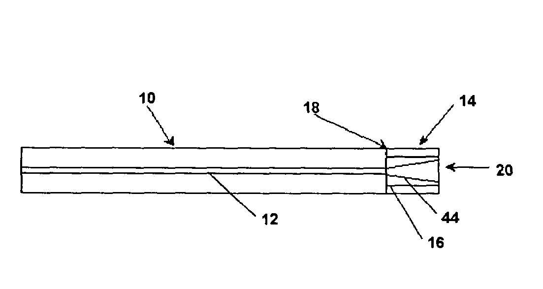
[0012]FIG. 1 illustrates the present invention as used with a single mode fiber (SMF) 10 having a relatively small core 12 which is spliced end to end along a splice line 18 to a short length of a Multi-Mode fiber (MMF) 14 having a relatively large core 16, matching in index with the fiber 10, and a polished end 20. Multi-mode fiber 14 is preferably a step index multi-mode fiber, however, in certain applications, a graded index multi-mode fiber may also be used or an optical fiber without cladding (air cladded) having approximately similar diameter as the single mode fiber.

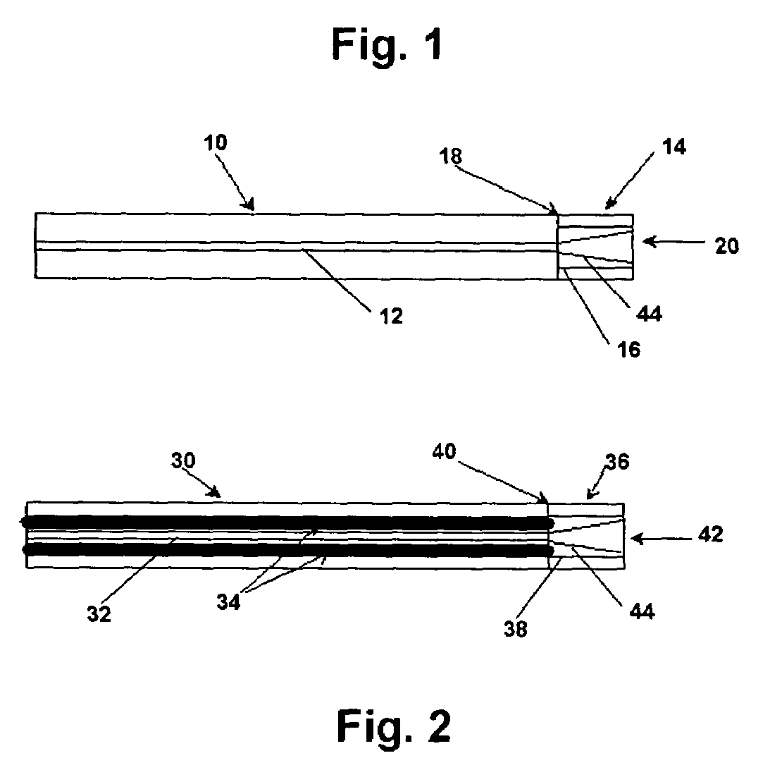
[0013]FIG. 2 illustrates the present invention as used with a Polarization Maintaining fiber (PMF) 30 having a relatively small core 32 and a pair of stress rods 34 which is spliced end to end along a splice line 40 to a short length of a Multi-Mode fiber 36 having a relatively large core 38, and matched in index with the fiber 30 and a polished end 42. Multi-mode fiber 36 is again preferably a step index multi-mo...


PUM

PropertyMeasurementUnit
lengthaaaaaaaaaa
angleaaaaaaaaaa
lengthaaaaaaaaaa

Abstract

Apparatus and methodology for the low coupling of optical fibers in high power applications. An end of a single mode optical fiber, or a polarization maintaining fiber, is cut and spliced to a relatively short segment of an index matched multi-mode fiber or an optical fiber without cladding (air cladded) having approximately similar diameter as the single mode fiber which in turn is coupled to the external device. The free end of the multi-mode fiber may be cleaved, polished and have an anti-reflection applied to it. The beam emitted by the small core of the single mode optical fiber expands into the larger core of the multi-mode fiber providing low loss high power coupling of the optical fiber to the external device.

Description

REFERENCE TO RELATED APPLICATIONS[0001]This application claims priority of U.S. Provisional application No. 60 / 608,283 filed Sep. 9, 2004.BACKGROUND OF THE INVENTION[0002]This application relates to optical fibers, and more specifically to apparatus and methodology for the efficient coupling of optical fibers in high power applications.[0003]High power performance of fiber lasers and fiber amplifiers is increasingly being required for a wide variety of applications and operating optical powers have increased enormously in recent years. Components used in these products are generally based on passive micro-optical parts assembled by attaching optical fibers (polarization maintaining fibers or single mode fibers) to them through input and output lenses. Such components, originally designed for low power applications (typically in the mW range), are now required to operate at powers ranging from several watts to kW levels. These components are not designed for, and cannot reliably oper...

Claims


Application Information

Patent Timeline
Patent Type & Authority Patents(United States)
IPC IPC(8): G02B6/00G02B6/02G02B6/26
CPCG02B6/262G02B6/2551
Inventor KOKKELINK, JAN W.FINDAKLY, TALAL K.
Owner LOCKHEED MARTIN CORP
Why Eureka
Try Eureka