Non-volatile differential dynamic random access memory

Inactive Publication Date: 2005-10-11
O2IC
29 Cites 224 Cited by

AI-Extracted Technical Summary

Problems solved by technology

Due to its larger memory cell size, an SRAM is typically more expensive to manufacture than a DRAM.
Therefore, where loss of data due to power failure or termination is unacceptable, a non-volatile memory is used to store the data.
Unfortunately, the non-volatile semiconductor memory is typically slower to operate than a volatile memory.
Furthermore, the non-volatile memory often requires a high voltage, e.g., 12 volts, to program or erase.
Such high voltages may cause a number of disadvantages.
The high voltage increases the power consumption and thus shortens the lifetime of the battery powering the memory.
The high voltage may degrade the ab...

Benefits of technology

[0015]According to the present invention, an improved memory device and method is provided. More particularly, the invention provides a semiconductor memory that has integrated non-volatile and dynamic random access memory cells. Although the invention has been app...

Abstract

In accordance with the present invention, a memory cell includes a pair of non-volatile devices and a pair of DRAM cells each associated with a different one of the non-volatile devices. Each DRAM cell further includes an MOS transistor a capacitor. The DRAM cells and their associated non-volatile devices operate differentially and when programmed store and supply complementary data. The non-volatile devices are erased prior to being programmed. Programming of the non-volatile devices may be done via hot-electron injection or Fowler-Nordheim tunneling. When a power failure occurs, the data stored in the DRAM are loaded in the non-volatile devices. After the power is restored, the data stored in the non-volatile devices are restored in the DRAM cells. The differential reading and wring of data reduces over-erase of the non-volatile devices.

Application Domain

Technology Topic

Embedded systemHot electron +6

Image

  • Non-volatile differential dynamic random access memory
  • Non-volatile differential dynamic random access memory
  • Non-volatile differential dynamic random access memory

Examples

  • Experimental program(1)

Example

[0030]According to the present invention, an improved memory device and method is provided. More particularly, the invention provides a semiconductor memory that has integrated non-volatile and Dynamic random access memory cells. Although the invention has been applied to a single integrated circuit device in a memory application, there can be other alternatives, variations, and modifications. For example, the invention can be applied to embedded memory applications, including those with logic or microcircuits, and the like.
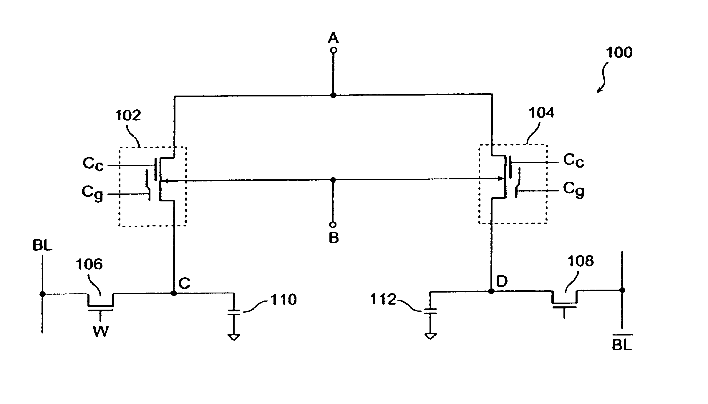
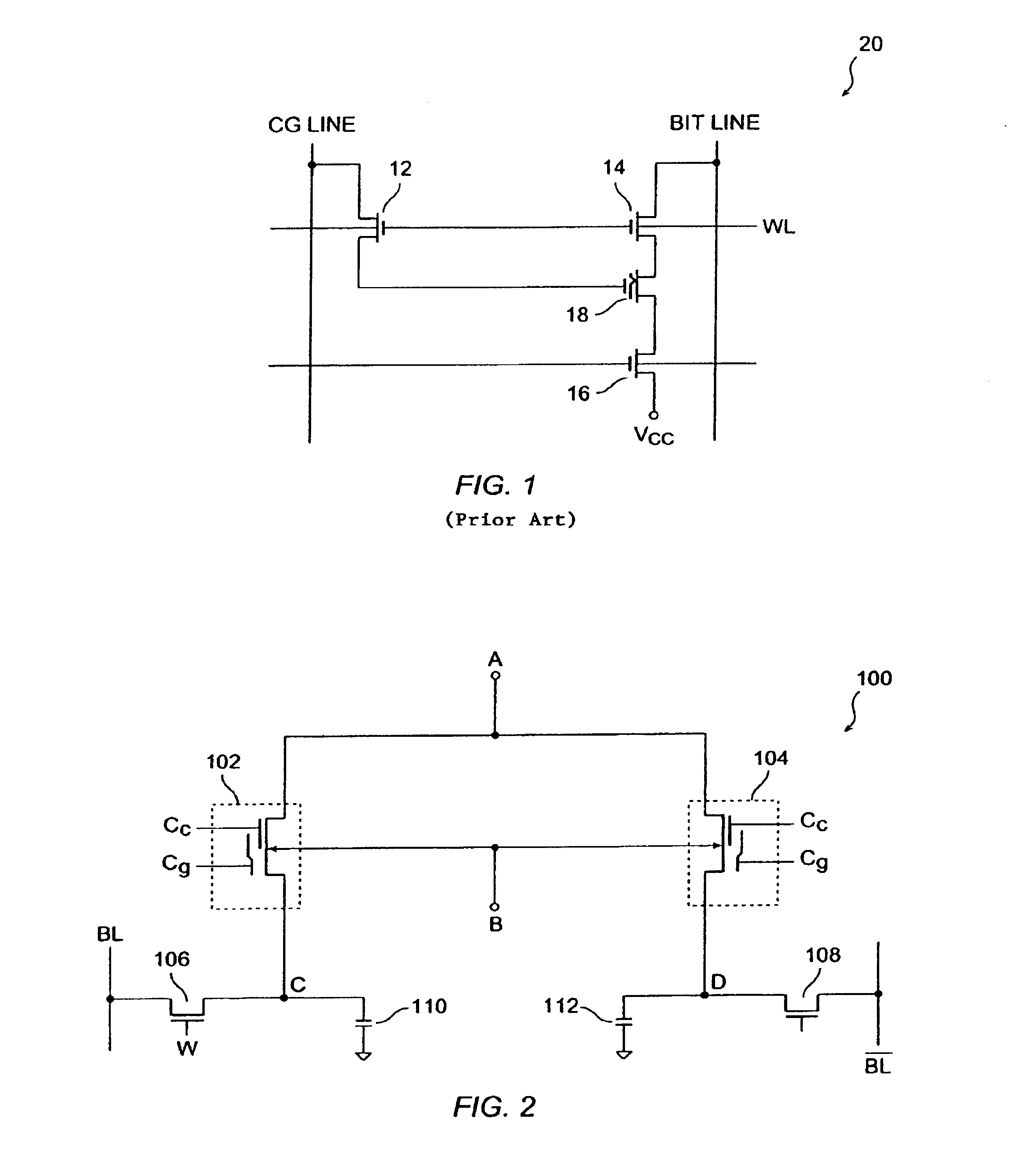
[0031]FIG. 2 is a transistor schematic diagram of a differential non-volatile dynamic random access memory (DRAM) 100 that includes both non-volatile and dynamic random access memory, in accordance with one embodiment of the present invention. This diagram is merely an example, which should not unduly limit the scope of the claims herein. One of ordinary skill in the art would recognize many other variations, modifications, and alternatives. Differential non-volatile DRAM memory (hereinafter alternatively referred to as memory) 100 includes non-volatile memory devices 102, 104, N-channel Metal-Oxide-Semiconductor (MOS) transistor 106 which together with the capacitance of node C forms a first DRAM cell, NMOS transistor 108 which together with the capacitance of node D forms a second DRAM cell.
[0032]Memory 100 includes terminals Cg, Cc, WL, BL and {overscore (BL)}. Memory 100 may be part of a memory array (not shown) disposed in a semiconductor Integrated Circuit (IC) adapted, among other functions, to store and supply the stored data. Terminals BL and {overscore (BL)} typically form true and complementary bitlines of such a memory array and terminal WL typically forms a wordline of such a memory array. In the following terminals BL and {overscore (BL)} are alternatively referred to as bitlines BL and {overscore (BL)}, respectively. In the following terminal WL is alternatively referred to as wordline WL.
[0033]The gate terminals of both MOS transistors 106 and 108 are coupled to wordline WL. The drain terminals of MOS transistor 106, 108 are respectively coupled to bit lines BL and {overscore (BL)}. The source terminals of MOS transistor 106, 108 are respectively coupled to nodes C and D. Non-volatile memory devices 102, 104 each have a guiding gate and a control gate. The guiding gate terminals of non-volatile cells 102, 104 are coupled to input terminal Cg of memory 100. The control gate terminals of non-volatile cells 102, 104 are coupled to input terminal Cc of memory 100. The drain terminals of non-volatile cells 102, 104 are coupled to input terminal A of memory 100. The source terminals of non-volatile cells 102, 104 are respectively coupled to nodes C and D. The body (i.e., the bulk) terminals of non-volatile cells 102, 104 are coupled to input terminal B of memory 100.
[0034]Non-volatile memory devices 102, 104 are described in copending application Ser. No. 10,394,417, entitled “Non-Volatile Memory Device”, the content of which is incorporated herein by reference in its entirety.
[0035]As described above, transistor 106 together with the capacitance of node C forms a first DRAM cell of memory 100. Similarly, transistor 108 together with the capacitance of node D forms a second DRAM cell of memory 100. In the embodiment of the memory shown in FIG. 2, the capacitance at node C, which is shown in FIG. 2 as capacitor 110, includes the source capacitance of transistor 106 as well as the source capacitance of non-volatile memory device 102. Similarly, the capacitance at node D, which is shown in FIG. 2 as capacitor 112, includes the source capacitance of transistor 108 as well as the source capacitance of non-volatile memory device 104. Therefore, it is understood that in embodiment 100 of the memory cell, capacitors 110 and 112 that store charges for the DRAM cells are intrinsic capacitances. It is understood that in other embodiments of the present invention, capacitors 110 and 112 are not intrinsic capacitors and are actively formed. For example, capacitors 110, 112 may be formed from two layers of poly-silicon insulated from one another by a dielectric, e.g., silicon dioxide, layer. In the following, the first and second DRAM cells of memory 100 are alternatively collectively referred to as the DRAM cell.
Programming the DRAM Cell
[0036]To store a 1 in the DRAM cell, voltage supply Vcc is applied to bitline BL and to wordline W1, while supply voltage Vss is applied to bitline {overscore (BL)}. In some embodiments of the present invention, supply voltage V is between 1.2 to 5.5 volts and supply voltage Vss is at the ground potential (i.e., 0 volts). Because transistor 106 is in a conducting state, the voltage of capacitor 110 is raised to voltage Vcc−Vt, where Vt is threshold voltage of any of the MOS transistors 106 and 108. Similarly, because transistor 108 is in a conducting state, the voltage of capacitor 112 is pulled to Vss volts (i.e., the voltage present on bitline {overscore (BL)}). Therefore, capacitor 110 is charged (to Vcc−Vt) and capacitor 112 is charged to 0 volts, thereby storing a 1 in the DRAM cell. Refresh cycles are carried out periodically to maintain the stored 1, as known by those skilled in the art.
[0037]To store a 0 in the DRAM cell, voltage supply Vcc is applied to bitline {overscore (BL)} and to wordline WL, while supply voltage Vss is applied to bitline BL. Because transistor 108 is in a conducting state, capacitor 112 is raised to voltage Vcc−Vt. Similarly, because transistor 106 is in a conducting state, capacitor 110 is pulled to Vss volts. Therefore, capacitor 112 is charged (to Vcc−Vt) and capacitor 110 is charged to 0 volts, thereby storing a 0 in the DRAM cell. Refresh cycles are carried out periodically to maintain the stored 0, as known by those skilled in the art.
[0038]FIG. 5 is a simplified timing diagram of the voltages applied to bitlines BL, {overscore (BL)} as well as to wordline WL during a programming cycle of the DRAM cell of memory 100. In accordance with FIG. 5, bitline BL and wordline WL are supplied with Vcc voltage while bitline {overscore (BL)} is supplied with Vss voltage. Accordingly, capacitor 110 is charged to supply voltage (Vcc−Vt) and capacitor 112 is pulled to the ground voltage. The voltages at capacitors 110, 112 are maintained at these values by periodically applying voltage Vcc to bitline BL and wordline WL, and applying voltage Vss to bitline {overscore (BL)}, as described above.
Reading the DRAM Cell
[0039]To read the data stored in the DRAM cell, supply voltage Vcc is applied to input terminal WL of memory 100, thereby coupling nodes C and D of memory 100 to bitlines BL and {overscore (BL)}, respectively. The voltages present on nodes C and D cause the bitline voltages to so change thus enabling a read circuitry, such as a sense amplifier (not shown) to sense this voltage difference and generate a corresponding output signal, as is known by those skilled in the art. FIG. 6 is a simplified timing diagram of the voltage applied to input terminal WL of memory 100 during a read cycle of the DRAM cell. In accordance with FIG. 6, input terminal WL is raised to supply voltage Vcc, thereby coupling capacitors 110, 112 to bit lines BL and {overscore (BL)}, respectively. Because capacitors 110, 112 respectively have high and low stored charges, bit lines BL and {overscore (BL)} are respectively raised to high and low voltages.
Erasing Non-volatile Devices
[0040]Non-volatile devices 102, 104 are erased before they are programmed. To erase the non-volatile devices 102, 104, terminals A, B of memory 100 are pulled to the Vss voltage. A relatively high negative voltage, e.g., −10 volts is applied to control gate terminal Cc, and guiding gate terminal Cg is either left floating or is coupled to the ground potential or receives a negative voltage. The application of these voltages causes electrons trapped in the nitride layer—formed between the respective control gate regions and the substrate regions of non-volatile devices 102, 104—to return to the substrate region and/or holes to be trapped in these nitride layers—due to hot hole injection—thereby neutralizing any trapped electrons. The tunneling of trapped electrons back to the substrate and/or trapping of holes in the respective nitride layers causes non-volatile devices 102, 104 to erase.
Programming Non-Volatile Devices Using Hot-Electron Injection
[0041]In accordance with the present invention, if the Vcc voltage supplied by, e.g. a battery, reduces below a certain value, or if there is an abrupt failure in the supply of voltage Vcc or if otherwise desired, data stored in the DRAM cell of memory cell 100 is stored in the non-volatile devices 102, 104 of memory 100. To achieve this, for example, a capacitor (not shown) is used to store charges while voltage supply is being turned off. The charges stored in the system capacitor are used by a high voltage generator circuit to generate the voltages required to operate the non-volatile memory cell. While the power supply reduction or failure occurs, data stored in the DRAM cell is loaded and stored in the non-volatile devices 102, 104 of memory 100. Non-volatile devices 102, 104 operate differentially in that if one of them, e.g., 102 is programmed to store a 1, the other one, e.g., 104 is programmed to store a 0. Therefore, during a read operation, if one of the non-volatile devices, e.g., 102 supplies a 1, the other one of the non-volatile devices, e.g., 104 supplies a 0.
[0042]In order to load the data stored in the DRAM cell in non-volatile devices 102, 104, non-volatile devices 102, 104 are first erased, as described above. Assume that the DRAM cell has stored a 1 therein, and therefore the voltages present on nodes C and D are at high and low levels respectively. To load this data in the non-volatile devices, 0 volt is applied to substrate terminal B of memory 100, a relatively high voltage Vpp in the range of, e.g., 5 to 12 volts is applied to terminal Cc of memory 100, a second voltage in the range of, e.g., 0.5 to 1.5 volts is applied to guiding gate terminal Cg, and a third voltage in the range of, e.g., 3 to 5 volts is applied to terminal A of memory 100. Voltage Vcc which is between 1.8 to 3.5 volts is applied to terminal WL and bitline BL; and 0 volt is applied to bitline {overscore (BL)}.
[0043]Because the voltage at the guiding gate of non-volatile device 102 is less than its source voltage, non-volatile device 102 is not turned on. Accordingly, no current flows from the source to the drain of non-volatile device 102 and thus no hot electron current is generated in the channel region of non-volatile device 102. Therefore, non-volatile device 102 is kept at the erase state and its threshold voltage is maintained at its erased value. Moreover, because there is a small difference between voltages at terminals A and Cg of non-volatile device 102 and because the difference between the voltage applied to control gate terminal Cc and terminal A (i.e., the drain terminal of non-volatile device 102) is relatively small, the voltage difference across the nitride layer of non-volatile device 102 is insufficient to cause Fowler-Nordheim tunneling of electrons to occur in non-volatile device 102. Accordingly, non-volatile device 102 maintains its previous discharge state and thus its threshold voltage remains at its erased value.
[0044]To load this data in the non-volatile devices, 0 volt is applied to substrate terminal B of memory 100, a relatively high voltage Vpp in the range of, e.g., 5 to 12 volts is applied to terminal Cc of memory 100, a second voltage in the range of, e.g., 0.5 to 1.5 volts is applied to guiding gate terminal Cg, and a third voltage in the range of e.g., 3 to 5 volts is applied to terminal A of memory 100. Voltage Vcc is applied to terminal WL and bitline {overscore (BL)}; and 0 volt is applied to bitline BL.
[0045]Because the source region of non-volatile device 104 (i.e., node D) is at 0 volt, and a voltage in the range of, e.g., 0.5 to 1.5 volts is applied to guiding gate terminal Cg, non-volatile device 104 operates in a weak turn-on (e.g., subthreshold) state as a channel is formed under its guiding gate. Because, a third voltage in the range of, e.g., 3 to 5 volts is applied to the drain region (i.e., terminal A), a current flows between the source and drain terminals of non-volatile device 104. The weak channel formed under the guiding gate of non-volatile device 104 remains close to the ground potential. Because the voltage applied to the control gate Cc of non-volatile device 104 is greater than its drain voltage applied, the voltage in the channel region formed under the control gate of non-volatile device 104 is close to the device's drain voltage, thereby causing a relatively large lateral electric field to develop near the gap separating the channel regions formed between the guiding gate and control gate of non-volatile device 104. The relatively high electric filed causes electrons passing through the gap—as they drift from the source to the drain region—to gain the energy required to surmount the silicon-oxide barrier and thus to flow into and get trapped in the nitride layer. The electrons are trapped in the nitride layer under the control gate and are positioned relatively away from the drain region of non-volatile device 104, thereby increasing the threshold voltage of non-volatile device 104. The charges remain trapped in non-volatile device 104 after power is turned off. Therefore, non-volatile device 104 maintains its higher threshold even after power is turned off. The increase in the threshold voltage of non-volatile 104 is used to restore the programming state of the DRAM cell when the power is subsequently restored, as described further below.
[0046]Therefore, non-volatile device 104 is programmed (i.e., charged) whereas non-volatile device 102 is not programmed (i.e., is not charged). Therefore, during each such cycle, one of the non-volatile devices of memory cell 100 is programmed and the other one of the non-volatile devices of memory cell 100 remains erased. It is understood that if the voltage across capacitor 110 is zero and the voltage across capacitor 112 is (Vcc−Vt) volts, after the above programming cycle, non-volatile device 102 is programmed and non-volatile device 104 remains in an erased stated. The differential programming, whereby one of the non-volatile devices is programmed while the other one remains erased, provides advantages that are described further below.
Reprogramming of the DRAM Cell
[0047]After power is restored, the DRAM cell is reloaded (i.e., reprogrammed) with data that it had prior to the power-off. As described above, this data is stored in the non-volatile devices differentially during the power-off. To reload this data in the DRAM cell, the Vcc voltage is applied to the terminals A and Cg of memory 100. Terminal B of memory 100 is pulled to the ground potential. A relatively small sensing voltage (i.e., less than the Vcc voltage) is applied to terminal Cc. The sensing voltage is selected so as to be larger than the threshold voltage of non-volatile device 102.
[0048]Because the gate-to-source voltage of non-volatile device 102 is greater than its threshold voltage and because of the presence of a voltage across the drain and source terminals of non-volatile device 102, a current flows between drain and source terminals of non-volatile device 102. Depending on the magnitude of the increase in the threshold voltage of non-volatile device 104, either non-volatile device 104 conducts no current or, alternatively conducts a current with a magnitude that is smaller than that conducted by non-volatile device 102.
[0049]The difference between the magnitude of the currents flowing through non-volatile device 102 and that, if any, flowing through non-volatile device 104, results in differential charging of capacitors 110, 112. Capacitors 110 and 112 are respectively charged to such that the difference between their voltages is Vcc, thereby causing the DRAM cell to store a 1.
[0050]As described above, during the power restore operation and when data stored in non-volatile devices 102 and 104 are read out, the current flow through non-volatile devices 102 and 104 is differential. Therefore, any change in the threshold voltages of non-volatile devices 102 and 104 due to over-erase also occurs differentially. The differential current flow through non-volatile devices 102 and 104, in accordance with the present invention, minimizes any data retention or read errors that may occur as a result of over erasing non-volatile devices 102 and 104 during erase cycles.
Recall of the DRAM Cell
[0051]To initiate a recall, both BL and {overscore (BL)} lines are pulled down to the ground potential. Input terminal WL is raised to the Vcc voltage, thus enabling both capacitors 110, 112 to discharge to the ground potential. Input terminals Cg is raised to the Vcc voltage to enable, in part, a conduction path to form between the DRAM cell and the non-volatile devices. Terminal A is also raised to supply voltage Vcc, and voltage in the range of e.g., 1.5 to 3 volts is applied to terminal Cc. Because, as described above, non-volatile device 104 is assumed to have a higher threshold voltage than non-volatile device 102, more current flows through non-volatile device 102 than through non-volatile device 104. Capacitors 110 and 112 are respectively charged to such that the difference between their voltages is Vcc, thereby causing the DRAM cell to store a 1.
[0052]FIG. 7 shows the voltages applied to various terminals of memory 100 during a recall procedure. As seen from FIG. 7, input terminals Cg and WL are raised to the supply voltage Vcc, thus enabling bitlines BL and {overscore (BL)} to receive the voltages a nodes C and D respectively. Application of a relatively low read voltage (sensing voltage) to terminal Cc causes capacitors 110, 112 to respectively restore their relatively high and low voltages.
[0053]The above embodiments of the present invention are illustrative and not limitative. The invention is not limited by the type of non-volatile memory transistor disposed in the memory cell of the present invention. Moreover, both N-channel and P-channel transistors may be used to from the DRAM as well as the non-volatile memory cells of the present invention. The invention is not limited by the type of integrated circuit in which the memory cell of the present invention is disposed. For example, the memory cell, in accordance with the present invention, may be disposed in a programmable logic device, a central processing unit, and a memory having arrays of memory cells or any other IC which is adapted to store data.
[0054]While the invention is described in conjunction with the preferred embodiments, this description is not intended in any way as a limitation to the scope of the invention. Modifications, changes, and variations, which are apparent to those skilled in the art, can be made in the arrangement, operation and details of construction of the invention disclosed herein without departing from the spirit and scope of the invention.

PUM

no PUM

Description & Claims & Application Information

We can also present the details of the Description, Claims and Application information to help users get a comprehensive understanding of the technical details of the patent, such as background art, summary of invention, brief description of drawings, description of embodiments, and other original content. On the other hand, users can also determine the specific scope of protection of the technology through the list of claims; as well as understand the changes in the life cycle of the technology with the presentation of the patent timeline. Login to view more.

Similar technology patents

Method for mold changing in heated glass sheet forming station

InactiveUS6418754B1Improve methodConfectioneryGlass drawing apparatusEngineeringHeated glass
Owner:GLASSTECH

Binaural hearing aid system and a method of providing binaural beats

ActiveUS20130202119A1Improve methodElectroencephalographyElectric tinnitus maskersBinaural hearing aidsBinaural beats
Owner:WIDEX AS

Classification and recommendation of technical efficacy words

Why Eureka
Try Eureka