
Transfer device having casing with elastic member

a transfer device and elastic member technology, applied in the direction of electrographic process equipment, instruments, optics, etc., can solve the problems of difficult to ensure even printing quality, difficult to achieve even printing quality, and large amount of data storage and handling, etc., to achieve strong transfer field, ensure unvarying print quality, and high density

Active Publication Date: 2005-10-11
SHARP KK
View PDF16 Cites 0 Cited by
  • Summary
  • Abstract
  • Description
  • Claims
  • Application Information

AI Technical Summary

Benefits of technology

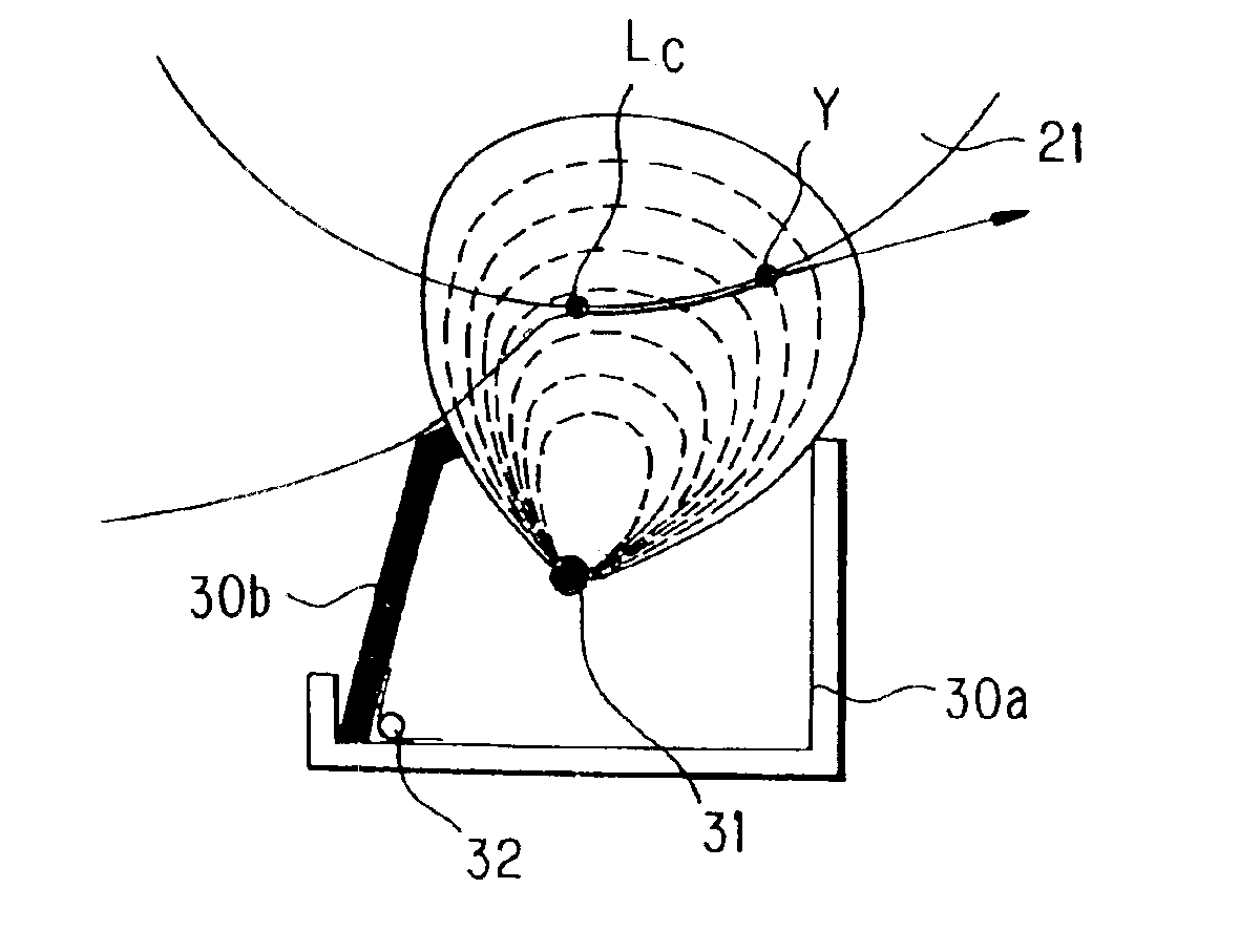
[0021]In contrast, when a sheet of a high rigidity is used as mentioned above, the inclination of the insulating element becomes large. Thereby, the transfer electric field produced by the transfer element is distributed in a narrower area before the transfer position and in a greater area after the transfer position and is formed to be relatively high in density at the transfer position. In this way, a stronger transfer field can be formed for a high rigidity sheet than for a low rigidity sheet. That is, the electric field becomes uneven with respect to the paper feed direction.
[0022]Consequently, since the strength of the transfer electric field varies depending on the inclination of the insulating element in conformity with the rigidity of the sheet even if a constant transfer voltage is continuously applied without regards to the sheet type, it is possible to assure the unvarying print quality without changing application of the transfer voltage in accordance with the sheet type as used to be done conventionally. Thus, it is possible to provide a simple configuration which can assure the unvarying print quality in conformity with the sheet type, without the necessity of providing complicated arrangements and processes as needed conventionally.
[0023]Further, in the transfer device of the present invention, since the upper end of the insulating element is beveled, the paper can be conveyed along the beveled surface. Therefore, it is possible to smoothly convey the sheet even if the upper end of the insulating element is arranged so as to abut the sheet in order to change the transfer electric field distribution as described above.

Problems solved by technology

Control of the transfer current in accordance with each sheet type is difficult to make by the above control, which results in causes of print failures and machine troubles.
Therefore, the transfer condition may change at the front part and the rear part over one sheet, causing difficulties in securing even printing quality.
Thus, in order to make control involving the measurement of environment, the controller needs to implement markedly complicated control and store and handle a huge amount of data.

Method used


Image

  • Transfer device having casing with elastic member
  • Transfer device having casing with elastic member
  • Transfer device having casing with elastic member

Examples


Embodiment Construction

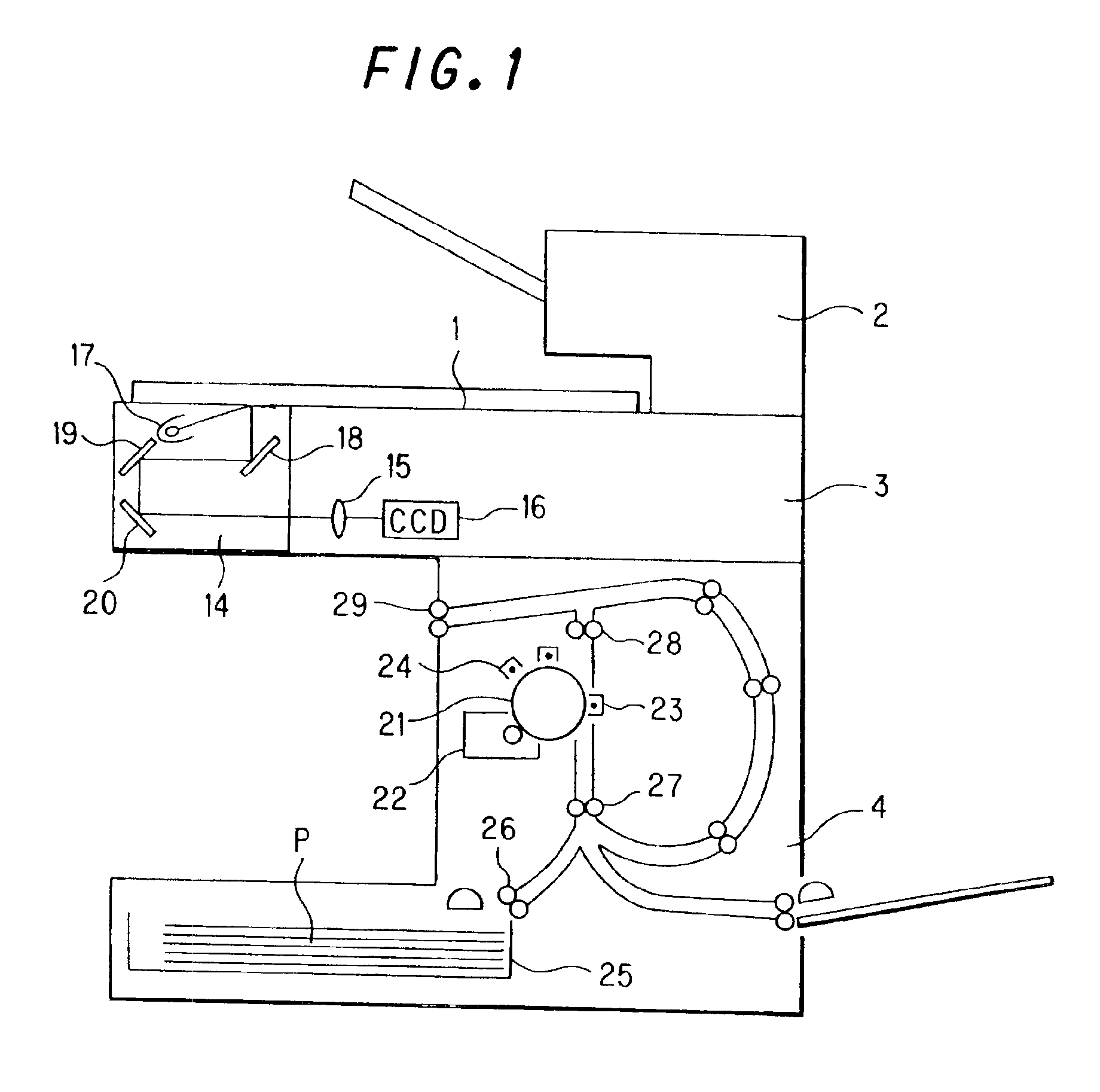
[0031]The embodiment of the present invention will hereinafter be described with reference to FIG. 1 to FIGS. 5A, 5B and 5C. It is noted that the present invention should not be limited to the description hereinbelow.

[0032]FIG. 1 is a sectional view showing an overall configuration of an image forming apparatus according to the present invention. As shown in FIG. 1, the image forming apparatus includes: an image reading unit composed of an original table 1, a document feed type image reader 2 and an image reading optical system 3; and an image forming portion 4. Image reading optical system 3 reads the image of an original placed on original table 1 or document feed type image reader 2, and includes a scanning unit 14, an image focusing lens 15 arranged in the optical path and a CCD (phototransducer) 16.

[0033]Scanning unit 14 illuminates the original and leads the reflected light from the original to CCD 16 by way of image focusing lens 15. Scanning unit 14 includes an exposure ligh...


PUM


Abstract

A transfer device includes: a discharge type transfer element for transferring the developer to a sheet by discharging electric charge to a static latent image support through the sheet so as to form an image of an original thereon; and a transfer casing accommodating the transfer element, wherein the side on the sheet's entrance side is formed of an electrically insulating element, and is constructed such that the transfer element and transfer casing are arranged so as to be offset to the upstream side with respect to the rotational direction of the static latent image support, along the outer peripheral surface thereof and so that the upper end of the insulating element blocks up into the paper feed path, and the insulating element is adapted to be bent toward the sheet feed direction by virtue of an elastic member.

Description

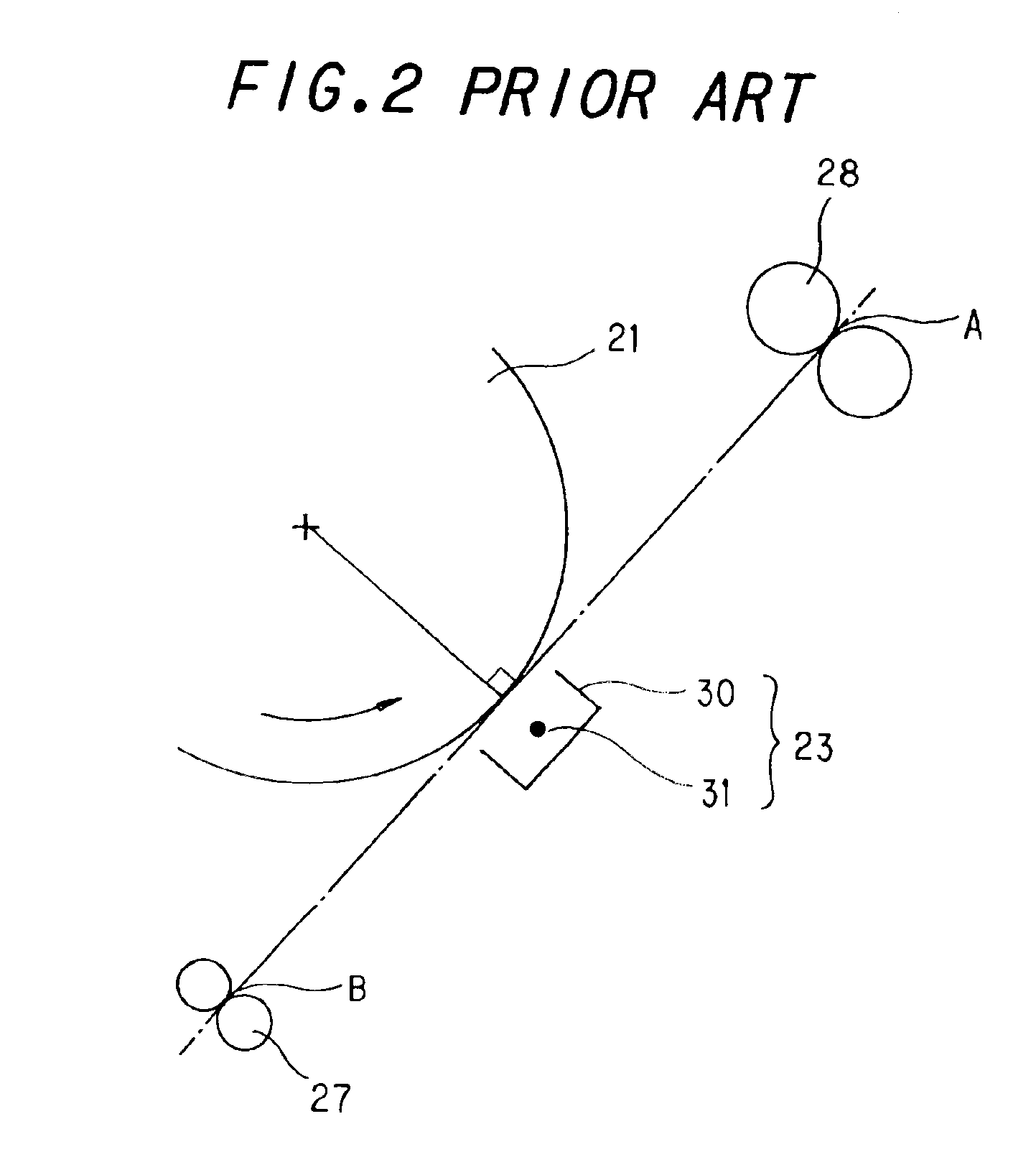
BACKGROUND OF THE INVENTION[0001](1) Field of the Invention[0002]The present invention relates to a discharge type transfer device for transferring the developer to the paper so as to reproduce an image from an original, in particular relating to a transfer device which provides unvarying transfer performance regardless of the type of sheet, by perceiving the difference of sheet rigidity.[0003](2) Description of the Prior Art[0004]Some transfer devices for use in electrophotographic image forming apparatuses such as copiers, printers and the like apply a transfer voltage by means of a transfer roller or transfer belt in order to transfer the developer (toner etc.) image onto an electrostatic latent image support (photoreceptor). Control of this transfer function is performed based on a constant-current system and is adapted to deal with change in transfer conditions within limits. For example, the control is made in accordance with change in the environmental conditions (high-temper...

Claims


Application Information

Patent Timeline
Patent Type & Authority Patents(United States)
IPC IPC(8): G03G15/16G03B15/00G03B15/16
CPCG03G15/1635G03G2215/1609
Inventor MURAKAMI, SUSUMUTOMIYORI, MINORUIWAKURA, YOSHIEIZUMI, HIDESHI
Owner SHARP KK
Learn More