Method for plugging holes in a printed circuit board

a printed circuit board and hole plugging technology, applied in the direction of resistive material coating, non-metallic protective coating application, lithographic mask, etc., can solve the problem of difficult surface circuit pattern, limit the densification degree of the board, and difficult surface circuit pattern pattern, etc. problem, to achieve the effect of smooth plugging of solder resist insulating material

Inactive Publication Date: 2005-10-18
LG INNOTEK CO LTD
View PDF11 Cites 18 Cited by
  • Summary
  • Abstract
  • Description
  • Claims
  • Application Information

AI Technical Summary

Benefits of technology

[0023]Therefore, an object of the present invention is to provide a hole plugging method for printed circuit boards and a hole plugging device in accordance therewith, capable of smoothly plugging a solder resist insulating material in a via h

Problems solved by technology

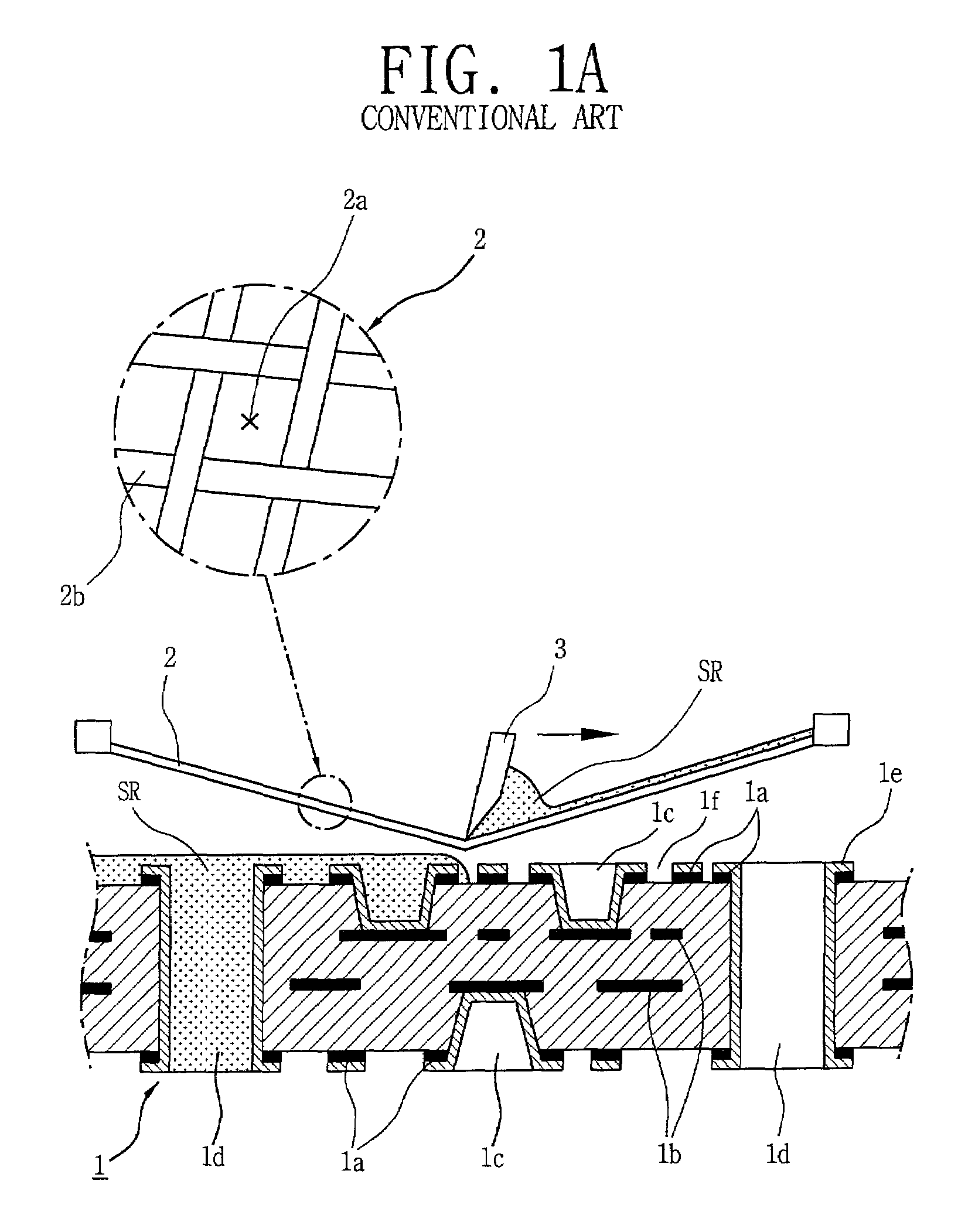
However, the interval between the through holes 1d can not be narrowed beyond a certain spacing and there is thus a limitation in the densification degree of the board when the sizes of tools and avoidance of damage to the board 1 in the processing are taken into consideration.
However, removing the solder resist SR afterwards by an abrasive process to expose the surface circuit pattern pattern 1a is not easy since the solder resist SR is coated covering the surface circuit pattern 1a completely and damages may result to the surface circuit pattern 1a in case of removing the solder resist SR by using a brush and the like.
Air bubbles remaining behind in the solder resist SR are discharged d

Method used


Image

  • Method for plugging holes in a printed circuit board
  • Method for plugging holes in a printed circuit board
  • Method for plugging holes in a printed circuit board

Examples


Embodiment Construction

[0047]Reference will now be made in detail to the preferred embodiments of the present invention, examples of which are illustrated in the accompanying drawings.

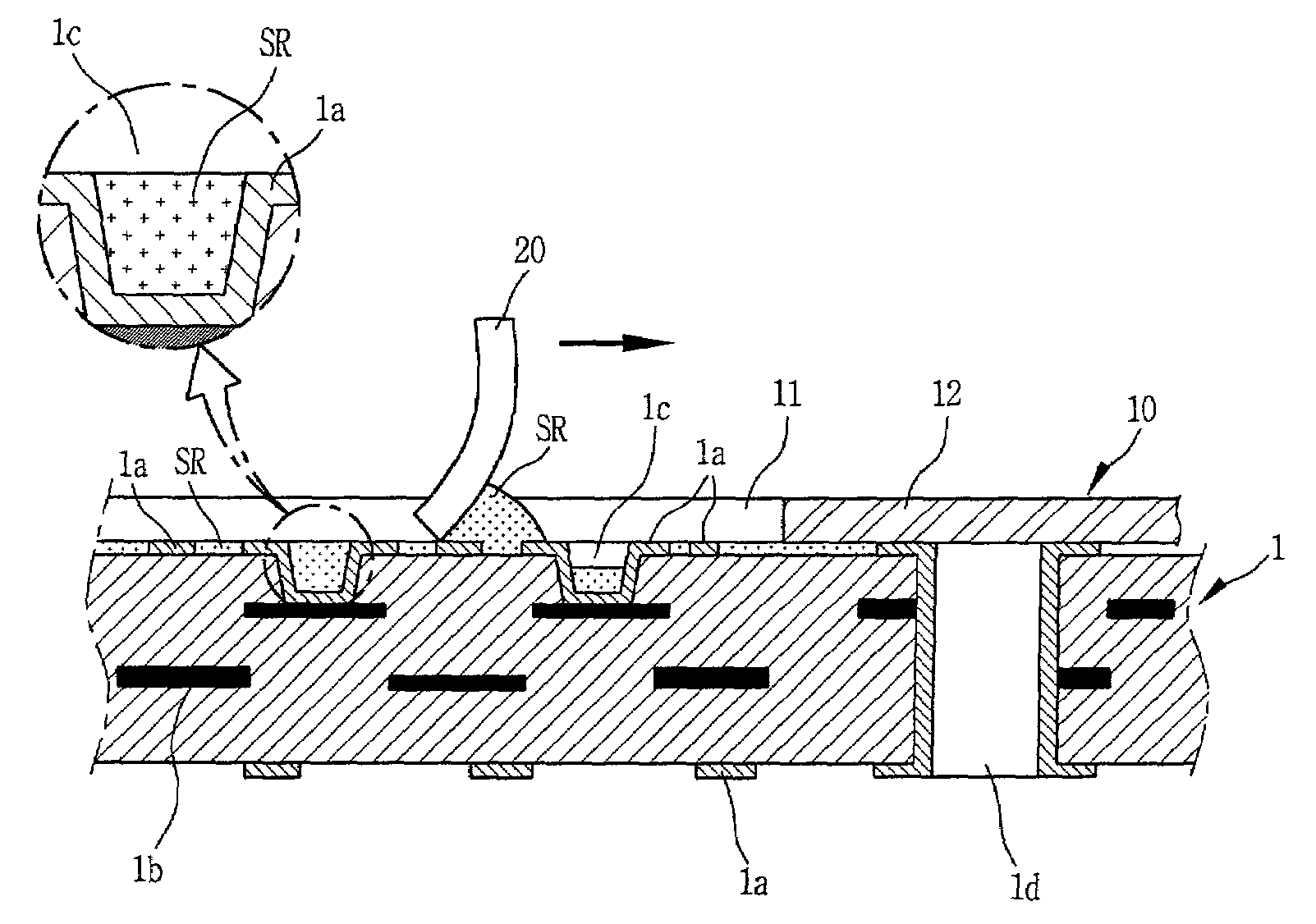
[0048]FIG. 3 is a perspective view showing a hole plugging device for printed circuit boards according to an embodiment of the present invention, FIG. 4 is a cross-sectional view showing the hole plugging device and method for printed circuit boards according to the embodiment of the present invention and FIG. 5 is a detail view showing a state where a hole is plugged in a printed circuit board according to the embodiment of the present invention.

[0049]Firstly, the printed circuit board includes a surface circuit pattern 1a and internal circuit conductors 1b are formed on and in a board 1 respectively, a via hole 1c formed to electrically connect the surface circuit pattern 1a and the internal circuit pattern 1b by a conductive layer 1e, and a through hole id formed to connect the both side surface circuit patterns 1a by the...


PUM

PropertyMeasurementUnit
Areaaaaaaaaaaa
Heightaaaaaaaaaa

Abstract

A hole plugging method for a printed circuit board, a hole plugging device in accordance therewith and a manufacturing method in accordance therewith where a mask for selectively exposing a via hole, a through hole and a surface pattern of the printed circuit board is positioned on the board having the via hole and the through hole to electrically connect circuit patterns formed on the surface of the board and in the board and an insulating material is plugged in the via hole by abutting and pushing the material on the surface of the board. Therefore, the insulating material can be plugged smoothly without a void, the processing is simplified by plugging the insulating material just to the height of the circuit pattern in a space between the circuit patterns and accordingly, damage to the circuit pattern can be prevented.

Description

BACKGROUND OF THE INVENTION[0001]1. Field of the Invention[0002]The present invention relates to a hole plugging method for printed circuit boards, a hole plugging device which carries out such method and a manufacturing method in accordance, and particularly, to a hole plugging method for printed circuit board and to a hole plugging device and a manufacturing method in accordance therewith which plugs holes in a printed circuit board with an insulating resin or solder resist by abutting a squeegee or doctor blade to an exposed hole using a mask capable of exposing a certain portion of a board or plugs resin or solder resist between circuit patterns with.[0003]2. Description of the Background Art[0004]Recently, integrated circuits (IC) have become more densified by an increase in the degree of integration according to the development of technology. Accordingly, it is required that a printed circuit board for mounting ICs become[0005]For meeting this necessity, currently, the printed...

Claims


Application Information

Patent Timeline
IPC IPC(8): H05K3/00H05K3/28H05K3/12H05K3/42H05K3/46
CPCH05K3/0094Y10T29/49144H05K3/28H05K2201/09509H05K2201/0959H05K2201/09881H05K2203/0278H05K2203/0557Y10T29/49155Y10T29/49135Y10T29/49126Y10T29/49128Y10T29/49117Y10T29/49124Y10T29/49165Y10T29/49167H05K3/1225
Inventor LEE, SUNG GUECHO, SUNG SIKKIM, YONG ILJANG, YONG SOONCHOI, HO SUNGKONG, SANG JINKIM, YOUNG HWAN
Owner LG INNOTEK CO LTD
Why Eureka
Try Eureka