Light-transmitting glass panel

a technology of light-transmitting glass and glass panels, which is applied in the direction of parallel plane units, special doors/window arrangements, doors/windows, etc., can solve the problems of reducing the heat transmission part due to radiation, reducing the transmittivity, and no longer displaying the inherent light-transmitting ability. , to achieve the effect of high thermal insulation performan

Inactive Publication Date: 2005-10-18
NIPPON SHEET GLASS CO LTD
View PDF5 Cites 40 Cited by
  • Summary
  • Abstract
  • Description
  • Claims
  • Application Information

AI Technical Summary

Benefits of technology

[0014]According to this construction, a light-transmitting glass panel having high thermal insulation performance with a thermal conductance of not more than 0.6 W / m2K can be provided.
[0015]Preferably, f(d,√S) is defined as f(d,√S)=5.2 d+5.5+(0.8 d+0.08)·√S. As a result, the above effect can be achieved reliably.
[0020]As a result, the thermal conductance of the light-transmitting glass panel can easily be made to be not more than 0.6 W / m2K.

Problems solved by technology

With multi-layered glass panels, it is already commonplace to fill with a noble gas such as argon or krypton having a lower thermal conductivity than dry air instead of dry air, or use low-emission (low-E) glass in which a low-emission layer having a low-emission function of reflecting infrared radiation has been applied onto a surface of the glass plate that contacts the dry air, thus reducing the part of heat transmission due to radiation; however, opening means having a thermal conductance of not more than 0.6 W / m2K have not yet been realized.
With such an opening means, one assumes that a noble gas would be used as the gas, and low-E glass would be used for the glass plates; the thickness of the opening means would be high, and hence installation into a window frame or the like would be complicated, and moreover the weight would be high, and furthermore even slight optical absorption by the glass would be multiplied and hence the transmittivity would be reduced and thus the inherent light-transmitting ability would no longer be sufficiently displayed.
However, heat will flow through the spacers, and hence the excellent thermal insulation performance obtained through the low pressure will be marred by the presence of the spacers.
However, even with a combination of a conventional thermally insulating vacuum glass panel, a noble gas, and low-E glass, it has not been possible to realize a glass panel having a thermal conductance of not more than 0.6 W / m2K.

Method used


Image

  • Light-transmitting glass panel
  • Light-transmitting glass panel
  • Light-transmitting glass panel

Examples


Embodiment Construction

[0032]Embodiments of the present invention will now be described with reference to the drawings.

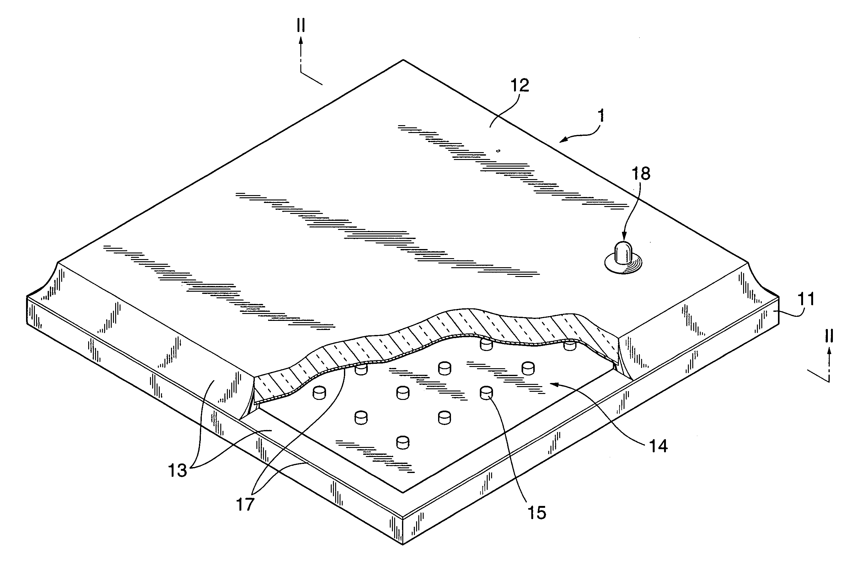
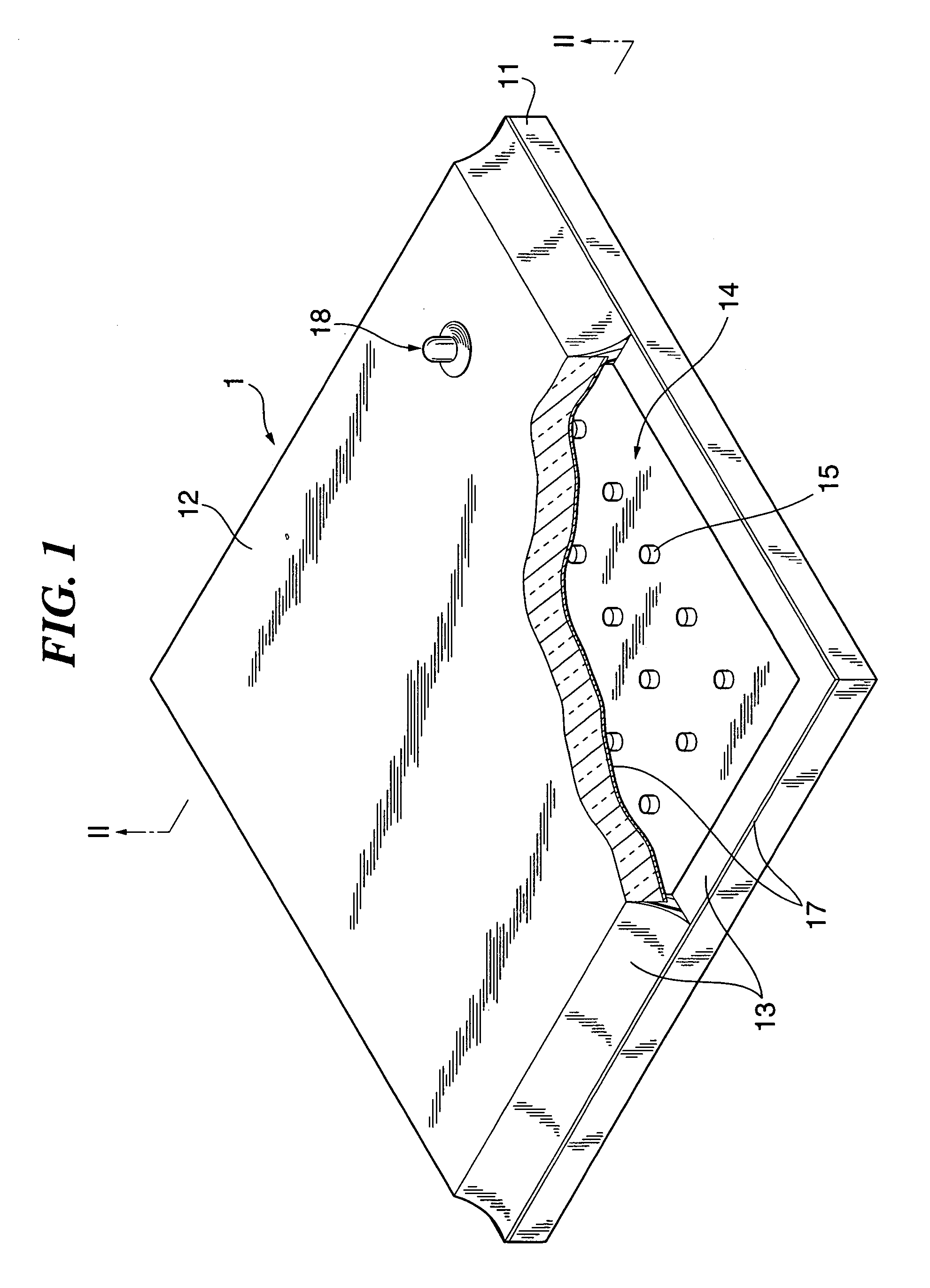
[0033]FIG. 1 is a perspective view of a light-transmitting glass panel according to an embodiment of the present invention.

[0034]In FIG. 1, the light-transmitting glass panel 1 according to the embodiment of the present invention is comprised of a pair of glass plates 11 and 12 that are hermetically joined together with one surface (an inner surface) of each thereof facing one another, the joining being via a sealing frame 13 that is provided at an outer peripheral portion of the glass plates 11 and 12 and fluidizes at low temperature, and the glass plates 11 and 12 having a hollow layer 14 formed therebetween, and pillars 15 that are substantially cylindrical spacers that are inserted into the hollow layer 14 as atmospheric pressure supporting members and determine the gap between the glass plate 11 and the glass plate 12.

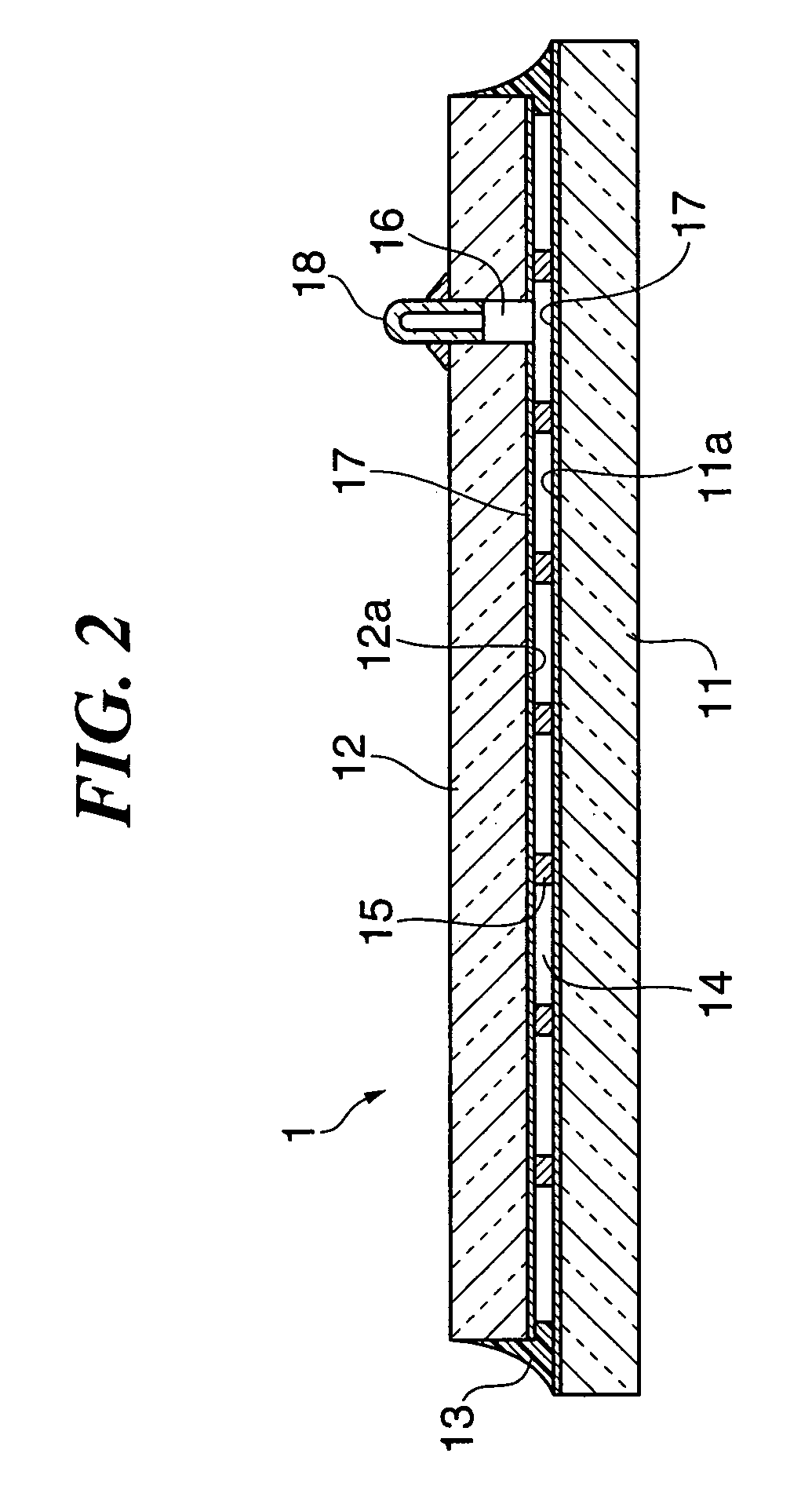
[0035]FIG. 2 is a sectional view taken along line II—II in FIG. 1....


PUM

PropertyMeasurementUnit
surface residual compressive stressaaaaaaaaaa
thicknessaaaaaaaaaa

Abstract

The light-transmitting glass panel 1 is comprised of a pair of glass plates 11 and 12 that are hermetically joined together with one surface of each thereof facing one another, the joining being via a sealing frame 13 that is provided at an outer peripheral portion of the glass plates 11 and 12 and fluidizes at low temperature, and the glass plates 11 and 12 having a hollow layer 14 formed therebetween, and pillars 15 that are substantially cylindrical spacers that are inserted into the hollow layer 14 as atmospheric pressure supporting members and determine the gap between the glass plate 11 and the glass plate 12. The pillars 15 are arranged in the hollow layer 14 in a matrix shape with a predetermined spacing, and taking the surface residual compressive stress of the glass plates 11 and 12 in MPa to be S, and the thickness of the glass plates 11 and 12 in mm to be d, the average spacing D in mm of the pillars 15 arranged in the hollow layer 14 satisfies the relationship D≦5.2d+5.5+(0.8d+0.08)·√S.

Description

[0001]This application is a continuation application of International Application PCT / JP03 / 05667 filed May 6, 2003.TECHNICAL FIELD[0002]The present invention relates to a light-transmitting glass panel, and in particular to a light-transmitting glass panel that can be used in opening means in the field of buildings such as residential buildings and non-residential buildings, the field of transport such as automobiles and other vehicles, ships and aircraft, the field of equipment such as freezers, freezer display cases and high-temperature high-humidity baths, and so on, and furthermore to a light-transmitting glass panel having incorporated therein a low-pressure multi-layered glass having high thermal insulation ability that can be applied to opening means for which energy saving is required.BACKGROUND ART[0003]In recent years, so as to keep down consumer energy demand and thus keep down emissions of CO2 gas which is feared to have an adverse effect on the global environment, the f...

Claims


Application Information

Patent Timeline
Patent Type & Authority Patents(United States)
IPC IPC(8): E06B3/67E06B3/663E06B3/66C03C27/06
CPCE06B3/66E06B3/6612E06B3/66304E06B3/6715Y02B80/24Y02A30/249Y02B80/22C03C27/06
Inventor MISONOU, MASAO
Owner NIPPON SHEET GLASS CO LTD
Why Eureka
Try Eureka