
Spray-coating device for a coating liquid

a coating liquid and coating technology, applied in the direction of applications, mechanical equipment, lighting and heating apparatus, etc., can solve the problems of increasing the weight of spray guns, affecting the accuracy of spray guns, so as to achieve the effect of less susceptible and more accurate operation

Inactive Publication Date: 2005-10-18
FINISHING BRANDS GERMANY
View PDF4 Cites 46 Cited by
  • Summary
  • Abstract
  • Description
  • Claims
  • Application Information

AI Technical Summary

Benefits of technology

[0007]The invention solves the problem to so design the spraycoating device that it shall be less susceptible to incur defects and that it shall operate more accurately with respect to controlling at least one compressed air flow for controlling the feed of coating liquid.
[0011]The invention's principle of measurement rests on acoustic measurements or on measuring the air pressure. The particular mechanism in the spray gun controls an air pulse which lasts the time needed by the liquid valve element to move from its initial position (closed or open valve seat position) to its final position (closed or open valve seat position). This air pulse may be detected using a valve element position sensor measuring air pressure or sound. The valve element position sensor may be mounted on the spray gun or preferably it may be configured separately from it and be connected to it by a hose. The air pulse is detected in the valve body position sensor by measuring the acoustics or pressure and it shall be used for control and / or signaling and preferably be converted into an electrical signal. This electrical signal is then amplified electronically and preferably by resort to a filter it shall also be rendered insensitive to ambient air pressures. In a special embodiment of the present invention, the electrical signal is digitized in such a way that an electrical pulse corresponding to the time pulse width of the air pulse is generated at the output of the valve element position sensor. As a result, an electrical, digital signal reflecting the time of motion of the liquid valve may be measured at the output of the valve element position sensor and can be directly analyzed by a control system or in a computer for purposes spraycoating operation. Such a device and such a procedure offer the advantage that the sensor does not require electrical leads and connectors that otherwise would have to be hooked up to the spray gun. This feature offers high safety and reliability of operation, soiling and jeopardy of explosions being precluded. The compressed air hose connecting the valve element position sensor to the spray gun may be integrated within one pack also containing hoses applying compressed air to the spray gun to act as compressed atomizing air and / or compressed shaping air and / or to the coating liquid.

Problems solved by technology

But electromagnetic sensors incur the drawback of being linked by a cable to the spray gun and by being electrically connected to said gun by an electric connector.
Specifically said connector is susceptible to becoming defective because illustratively containing a small and easily deforming prong acting as the connecting element, and moreover said electrical cable increases the spray gun weight and degrades its freedom of motion.
Before opening the liquid feed valve discharging and atomizing the coating liquid, the compressed atomizing air and the compressed shaping air already must have been applied in order that the coating liquid shall exhibit from its beginning the required shape and the spray jet quality necessary to optimally coat an object to be coated, because otherwise low quality of coating would ensue.

Method used


Image

  • Spray-coating device for a coating liquid
  • Spray-coating device for a coating liquid
  • Spray-coating device for a coating liquid

Examples


Embodiment Construction

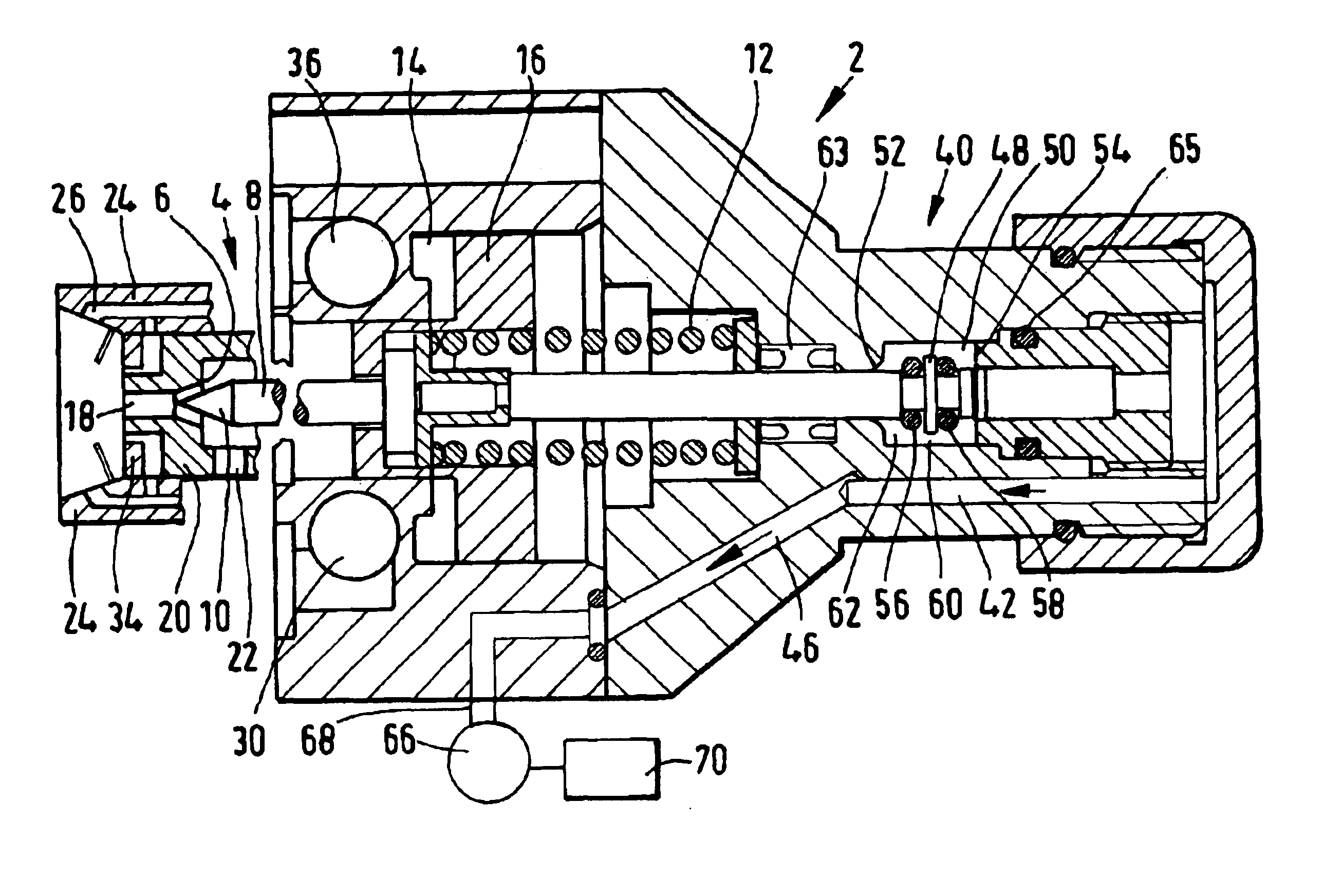
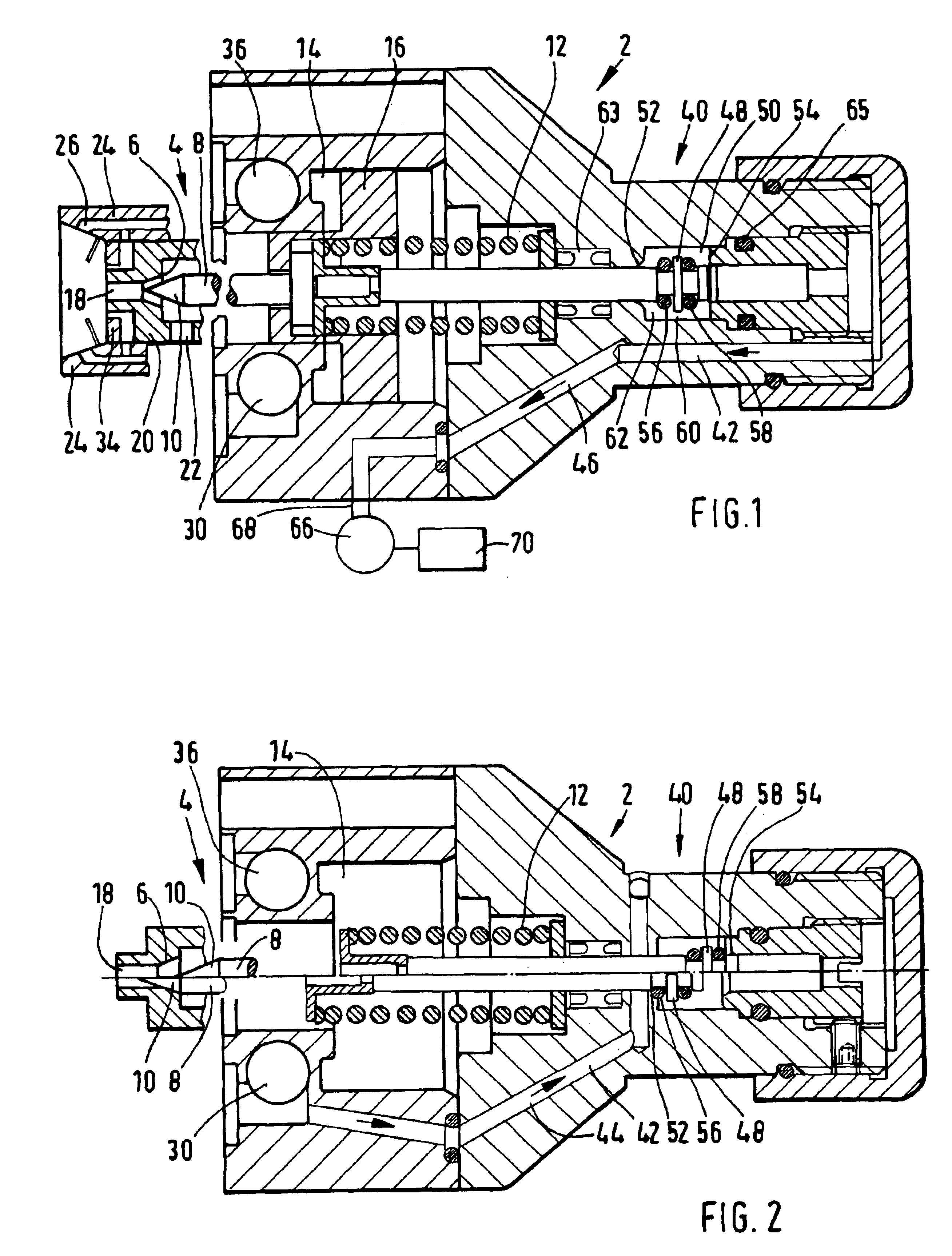
[0018]FIGS. 1 and 2 show an axial section of a liquid spraycoating device of the invention for coating liquid and include a coating liquid spray gun 2 containing a liquid feed valve 4 fitted with a liquid valve seat 6 and a liquid valve element 8 in the form of a needle having a conical tip 10. The liquid valve element 8 is linearly displaceable relative to the liquid valve seat 6 between a fully closed liquid valve position shown in the lower half of FIG. 2 and a fully open liquid valve position shown in the upper half of FIG. 2. FIG. 1 shows the valve element 8 in an arbitrary intermediate position between the open and closed liquid valve positions of FIG. 2.

[0019]The liquid valve element 8 is biased by a compression spring 12 toward the closed position and is driven against the force of said spring 12 by the compressed control air in a pressurized control chamber 14 on a control piston 16 which is ganged to the liquid valve element 8 to attain joint linear motion.

[0020]The liquid...


PUM


Abstract

A spraycoating device includes at least one coating liquid spray gun (2) which contains a measuring valve device (40) opening or closing a compressed gas measuring valve flow path (42) depending on the positions of a liquid feed valve (4). The measurement of the compressed gas flow allows automatically determining whether the liquid feed valve (4) is situated in a fully close or a fully open position or in an arbitrary intermediate position thereto.

Description

FIELD OF THE INVENTION[0001]The present invention relates to a spraycoating device for a coating liquid. In particular, the present invention relates to a spraycoating device containing a coating-liquid spray gun comprising a liquid feed valve fitted with a valve seat and with a valve element for said liquid, said valve element for said liquid being displaceable relative to said seat between a closed and an open valve position.BACKGROUND OF THE INVENTION[0002]The spraycoating device is composed at least of a spray gun exhibiting the features of the present invention. However this invention also concerns a spraycoating device fitted in addition to said spray gun with a control unit or at least a sensor that are connected to said gun. A spray gun of this kind for coating liquid is known from the European patent document 1,048,359 A2. Moreover it is known from the field of practice to fit the spray gun with an electromagnetic sensor determining whether the valve element for the liquid ...

Claims


Application Information

Patent Timeline
IPC IPC(8): B05B7/02B05B7/12B05B1/30F16K37/00
CPCF16K37/0066B05B7/1254B05B1/3046B05B1/306B05B7/1272B05B7/12
Inventor DANKERT, MANFRED
Owner FINISHING BRANDS GERMANY
Learn More