Object detecting device and method with means for controlling direction of scan by electromagnetic waves

Active Publication Date: 2005-10-18
OMRON AUTOMOTIVE ELECTRONICS CO LTD
View PDF3 Cites 27 Cited by
  • Summary
  • Abstract
  • Description
  • Claims
  • Application Information

AI Technical Summary

Benefits of technology

[0004]It is therefore an object of this invention to make it possible wit

Problems solved by technology

This method requires a plurality of laser diodes because laser light must be transmitted in different vertical directions and the structure of the laser radar becomes complex.
Since use is made of laser light which spreads widely in the vertical direction, f

Method used


Image

  • Object detecting device and method with means for controlling direction of scan by electromagnetic waves
  • Object detecting device and method with means for controlling direction of scan by electromagnetic waves
  • Object detecting device and method with means for controlling direction of scan by electromagnetic waves

Examples


Example

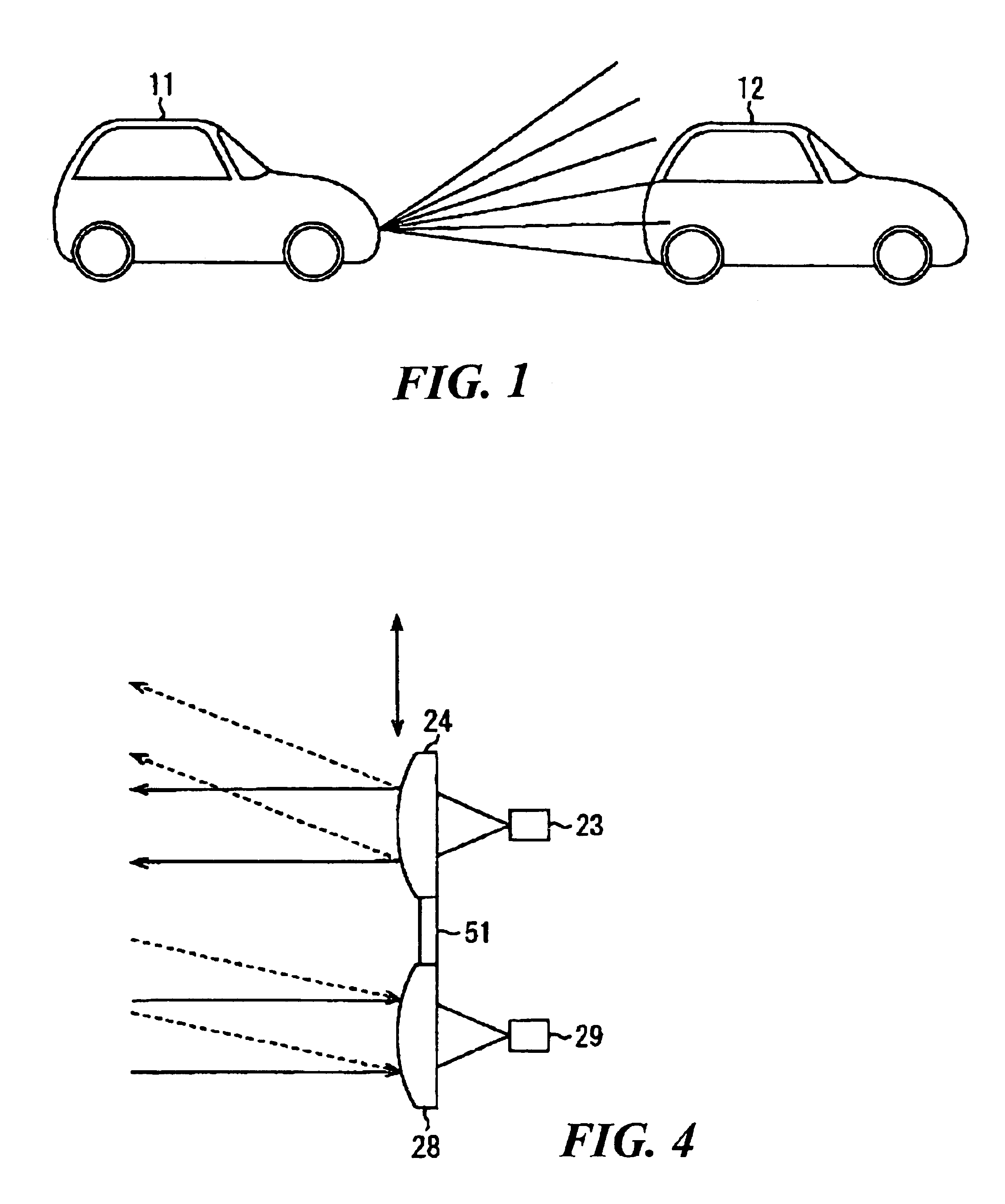
[0030]The invention is described next by way of an example with reference to drawings. FIG. 1 is a schematic drawing for showing the manner of using an example of laser radar system embodying this invention for a vehicle, illustrating a vehicle 11 transmitting laser light towards another vehicle 12 and estimating the distance therebetween from the reflected light from the other vehicle 12.

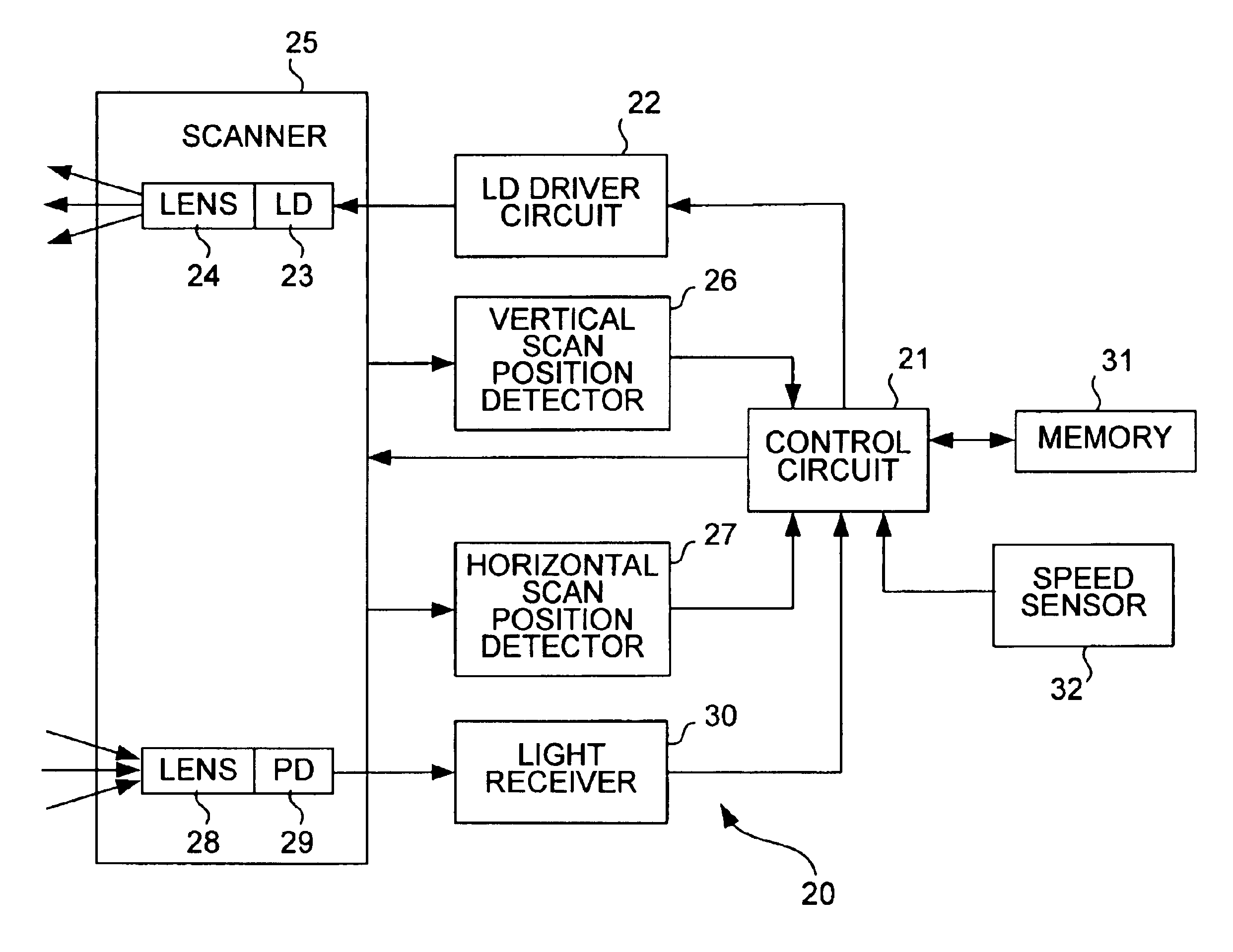
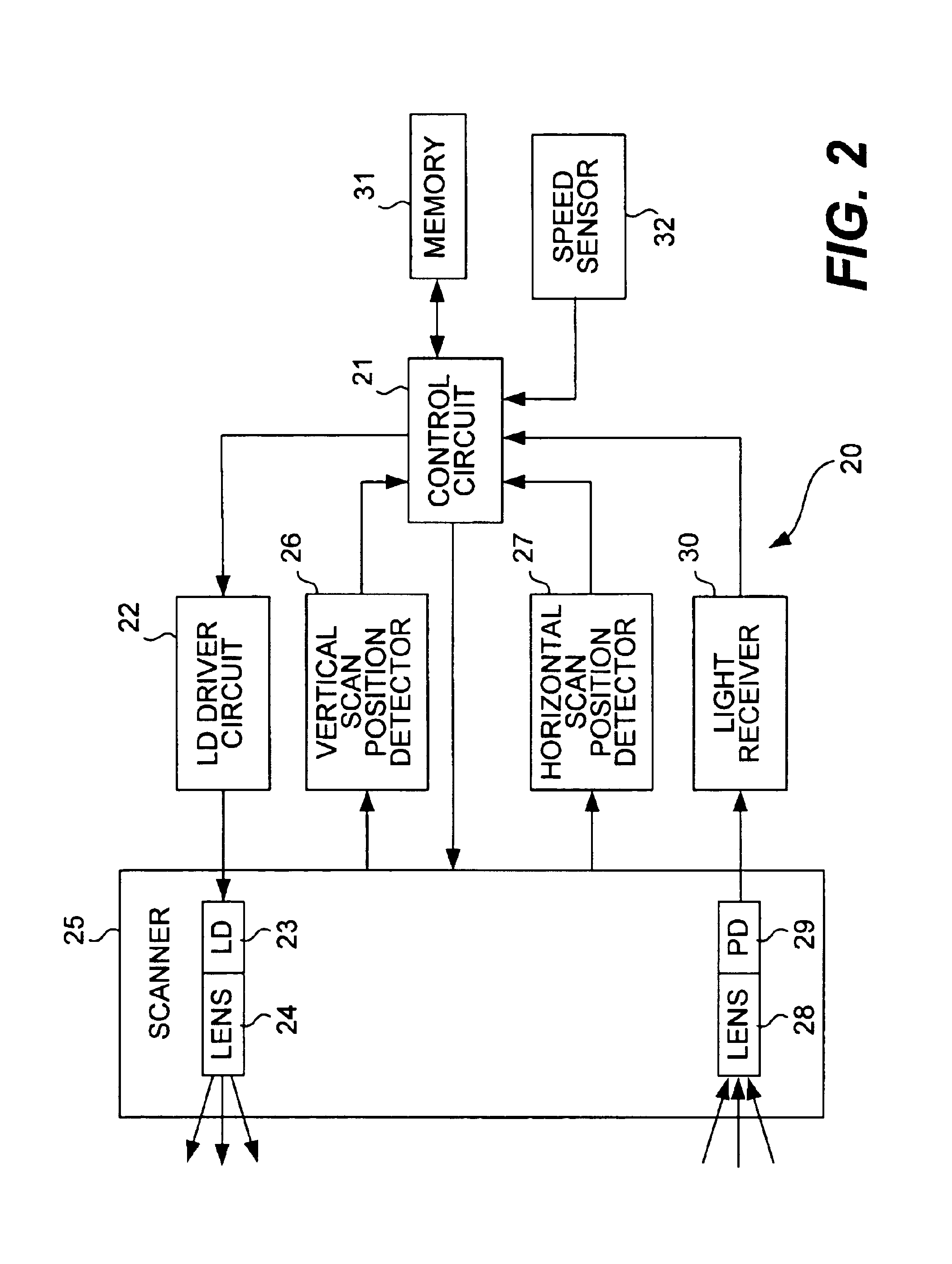
[0031]FIG. 2 is a block diagram for showing the structure of a laser radar 20 serving as a distance detector installed on the vehicle 11. A laser diode (LD) driver circuit 22 controls the light emission from an laser diode (LD) 23 on the basis of a drive signal generated by a control circuit 21. A scanner 25 serves to scan a specified scan area with laser light generated by the LD 23. The laser light emitted from the scanner 25 is transmitted in the direction of motion (to the right in FIG. 1) of the vehicle 11 through a transmission lens 24. A vertical scan position detector 26 and a horizontal sc...


PUM


Abstract

An object detecting device has components which emit electromagnetic waves by scanning a scan range in horizontal and vertical directions, receive reflected waves, obtain signal level of the received reflected waves, calculate a correction value based on vertical position of the zone in the scan range where the level of the received waves is the highest and the center position of the scan range in the vertical direction, and correct the center position in the vertical direction of the scan range based on the calculated correction value.

Description

[0001]This application claims priority on Japanese patent application 2002-293743 filed Oct. 7, 2002.BACKGROUND OF THE INVENTION[0002]This invention relates to an object detecting device and method. This invention relates more particularly to an object detecting device conveniently usable on an automobile for detecting another vehicle and a method of using such a device.[0003]There have been known laser radars of the type to be carried on a vehicle for transmitting a laser light beam in the direction of its motion, receiving its reflected waves to thereby detect a front-running vehicle and automatically outputting an alarm signal in order to prevent a collision. In order to prevent erroneous recognition of an object by such a detecting device due to the sloping of its detection area caused by errors in the attachment of the laser radar onto the vehicle or the condition of setting on the vehicle, Japanese Patent Publication Tokkai 2000-56020 has disclosed a method of transmitting las...

Claims


Application Information

Patent Timeline
IPC IPC(8): G01S17/93G01S17/00G01S17/42B60R21/00G01S17/931G01S7/40G01S7/48G01S7/497
CPCG01S7/4972G01S17/42G01S17/936G01S17/931
Inventor MIYAZAKI, HIDENORIARITA, SATORUSHIRAI, TAKASHI
Owner OMRON AUTOMOTIVE ELECTRONICS CO LTD
Why Eureka
Try Eureka