

Pogo contactor assembly for testing of and/or other operations on ceramic surface mount devices and other electronic components
- Summary
- Abstract
- Description
- Claims
- Application Information
AI Technical Summary
Benefits of technology
Problems solved by technology
Method used
Image

Examples
Embodiment Construction
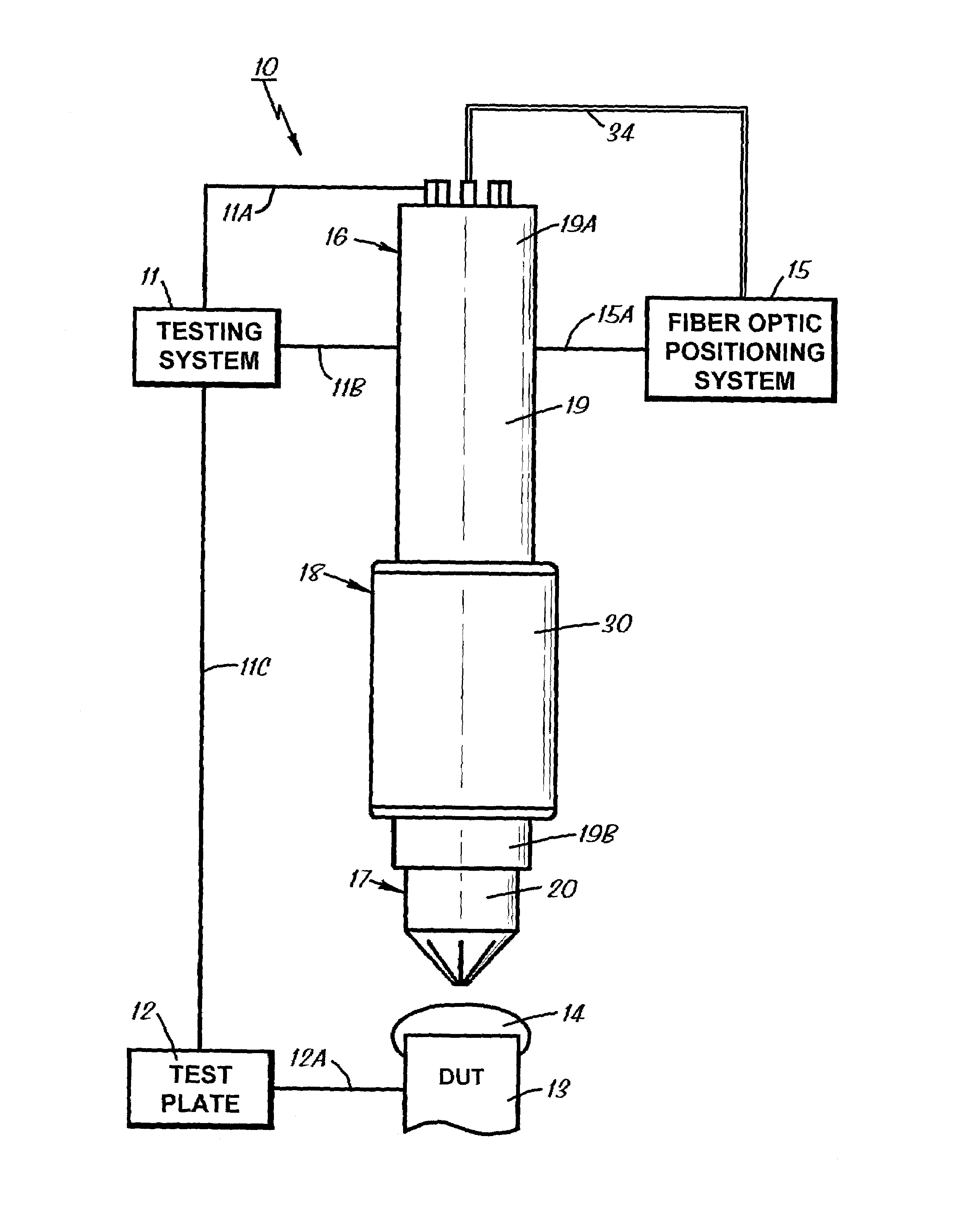
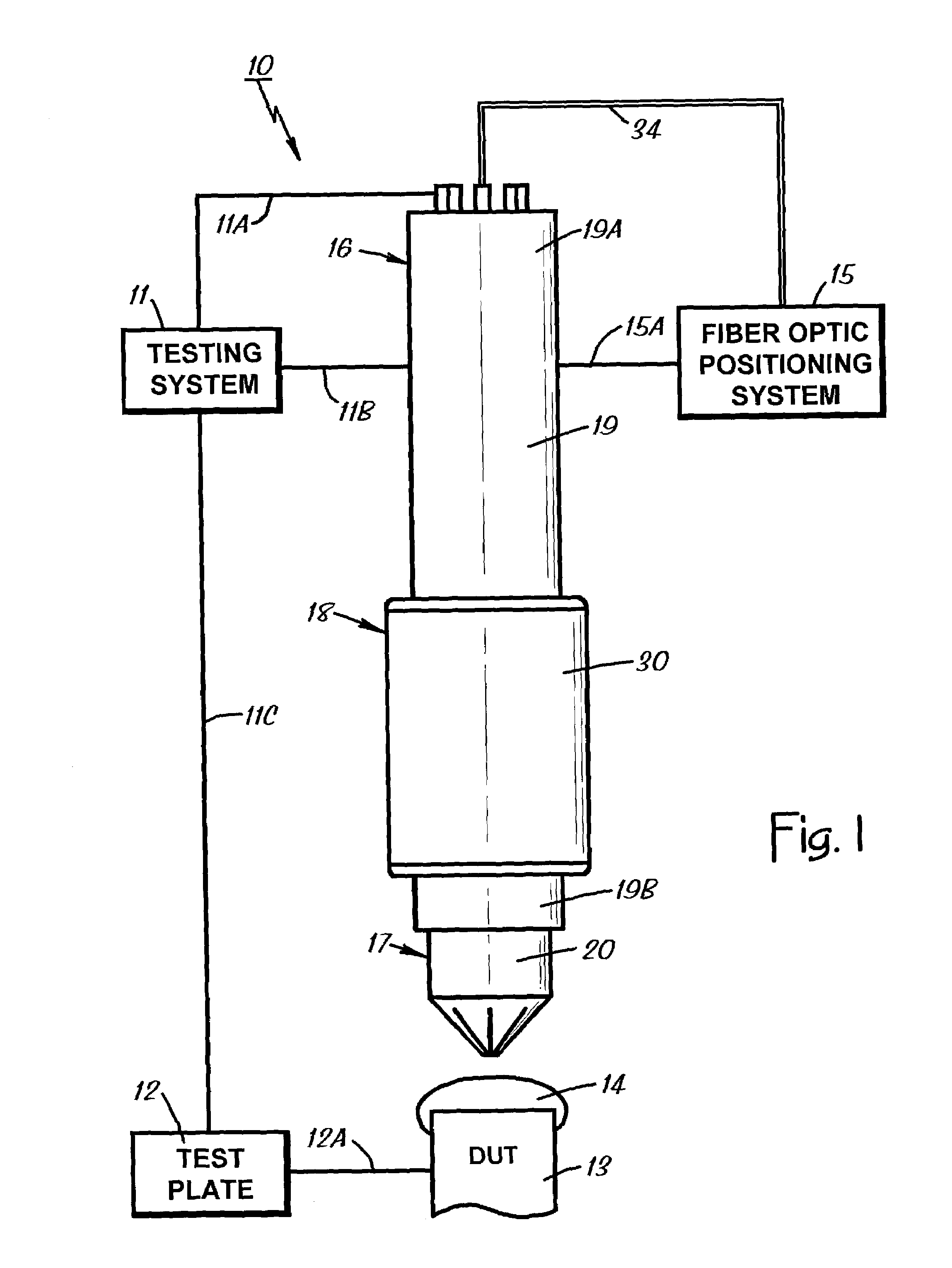
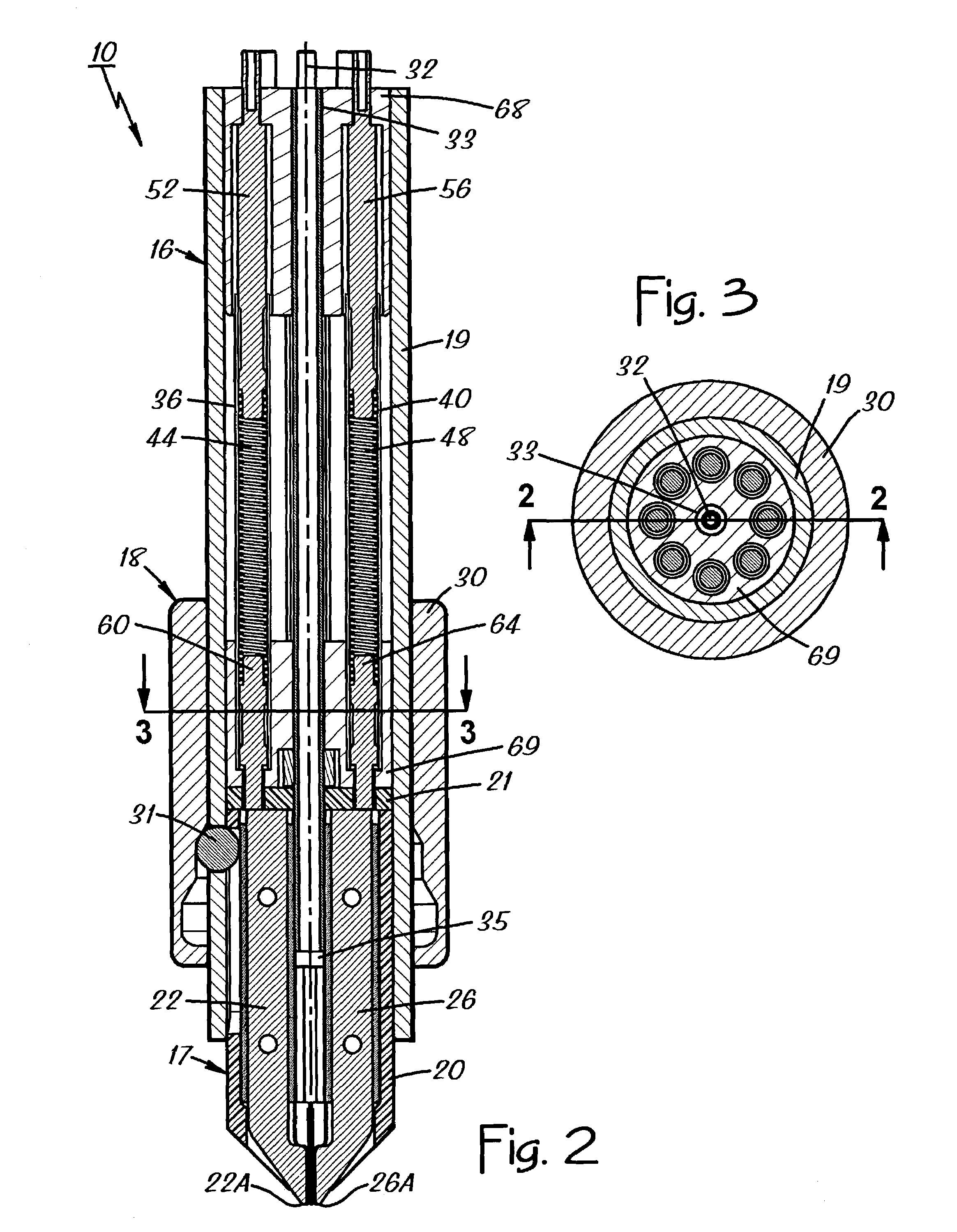
[0035]FIGS. 1–7 of the drawings show various aspects of a contactor assembly 10 constructed according to the invention. It is shown in FIG. 1 in its typical environment, mounted on a component testing system 11 that is depicted diagrammatically. The testing system 11 is coupled to the contactor assembly 10 electrically, as represented in FIG. 1 by a signal line 11A, and mechanically as represented by a line 11B. The testing system 11 holds a test plate 12 as represented by a line 11C, and the test plate 12 holds a DUT 13 as represented by a line 12A. The contactor assembly 10 couples test signals between the testing system 11 and a DUT terminal 14 on the DUT 13, while a fiber optic positioning system 15 precisely positions the contactor assembly 10 relative to the DUT terminal 14 as represented by a line 15A. United States patent application having Ser. No. 10 / 097,464 provides some related information about contactor assemblies used with component testing systems, and that patent ap...
PUM
 Abstract
Description
Claims
Application Information