System to measure density, specific gravity, and flow rate of fluids, meter, and related methods

a technology of density measurement and flow rate, applied in the field of flow meters, can solve the problems of high cost and complexity of density measurement techniques, high cost and high cost of both instruments, and the need for frequent maintenance by highly skilled technicians

Active Publication Date: 2005-10-25
SAUDI ARABIAN OIL CO
View PDF16 Cites 69 Cited by
  • Summary
  • Abstract
  • Description
  • Claims
  • Application Information

AI Technical Summary

Benefits of technology

[0014]In view of the foregoing, embodiments of the present invention advantageously and uniquely integrate well-known industrial flow meter operating principles into a single industrial instrument. Embodiments of the present invention provide a simple, low-cost flow metering components integrated into a single flow metering device capable of measuring process fluid density as well as flow rate. Advantageously, embodiments of the present invention contain no moving parts and very little required maintenance.
[0018]The process density meter includes a vortex-shedding body positioned within the fluid passageway of the pipeline. The vortex-shedding body is preferably in the form of a three-dimensional bluff body having an upstream side and a plurality of downstream sides. In the preferred configuration, the vortex-shedding body is adapted to connect to the pipeline or pipeline housing on opposite sides within the fluid passageway of the pipeline. The vortex-shedding body includes an upstream surface positioned transverse to the longitudinal axis of the pipeline which have or contain a plurality of total pressure inlet ports positioned in the upstream surface. The vortex-shedding body also includes a plurality of downstream surfaces which have or contain a plurality of static pressure inlet ports positioned in at least one of the downstream surfaces. The total pressure ports and static pressure ports can be used in conjunction with a differential pressure sensing device such as a pitot-type differential pressure meter, described below. The plurality of upstream ports and downstream ports provide the ability to average the pressures across the vortex-shedding body within the pipeline, thus improving meter accuracy, and serve to resist plugging, minimizing the need for maintenance on the process density meter. Having the plurality of downstream surfaces, rather than a cylindrical shape, can improve vortex-shedding and delineation between the total and static pressures. The vortex-shedding body also can have a thermal sensor inlet port, typically positioned in the upstream surface, and correspondingly, a thermal sensor outlet port positioned in at least one of the downstream surfaces. A fluid passageway extends between the thermal sensor inlet port and the thermal sensor outlet port so that fluid flowing through the pipeline passes therethrough for use with a thermal flow sensing device such as the thermal flow meter.
[0023]Advantageously, in an embodiment of the present invention, the process density meter can include a thermal flow measuring device, such as a thermal flow meter, appropriately positioned to produce a mass flow rate signal indicative of a mass flow rate of fluid when flowing through the pipeline. The thermal flow meter can have one or multiple thermal flow meter elements installed in, on, or next to the leading edge of the vortex shedding meter body, but is preferably positioned within the vortex-shedding body to minimize electrical wiring requirements.
[0051]Advantageously an embodiment of the present invention can provide an instrument intended for use in industrial combustion processes using low molecular weight hydrocarbon fuel gases, but may be used in any industrial process where simple, low-cost, and maintenance fuel density and fluid flow rate measurements are desired.

Problems solved by technology

Both direct BTU measurement and density measurement techniques are typically expensive and complex.
However, both of these instruments, though accurate, are very costly and require highly skilled technicians to conduct frequent maintenance.
The typical gas chromatographs can provide 0.1% BTU measurement accuracy but are very complex.
Flame BTU analyzers can give between 0.4-2.0% BTU measurement accuracy but are also very complex.
The meters, however, typically cannot accurately measure low molecular weight gas density.
Thus, it is not possible to derive density or mass flow rate from the volumetric flow rate measurement, alone, especially where the fluid is in a gaseous form.
Because it requires breaching the production pipe for each of the static and dynamic ports of the differential pressure measuring device, however, the device, is complex to install.
Additionally, it is not sufficiently accurate because it does not directly provide pressure and temperature compensated density.
Temperature is monitored and can sometimes be applied to attempt to correct the calculated gas density during an interim where the flow velocity is outside the overlap region, and thus, unable to provide for a truly updated gas density calculation.
The device does not have a combined unit that measures fluid density at substantially all operational flow rates, and therefore cannot provide for a continuously updated gas density much less a continuously updated gas density output.
Also, the device is truly two separate devices as the separate thermal flow meter is positioned in a separate meter passage than that of the vortex flow meter and is thus more difficult and complex to install.

Method used


Image

  • System to measure density, specific gravity, and flow rate of fluids, meter, and related methods
  • System to measure density, specific gravity, and flow rate of fluids, meter, and related methods
  • System to measure density, specific gravity, and flow rate of fluids, meter, and related methods

Examples


Embodiment Construction

[0067]The present invention will now be described more fully hereinafter with reference to the accompanying drawings, which illustrate embodiments of the invention. This invention may, however, be embodied in many different forms and should not be construed as limited to the illustrated embodiments set forth herein. Rather, these embodiments are provided so that this disclosure will be thorough and complete, and will fully convey the scope of the invention to those skilled in the art Like numbers refer to like elements throughout. Prime notation, if used, indicates similar elements in alternative embodiments. Note, the term “adjacent” as used herein refers to a position that is within, on, or near the object referenced.

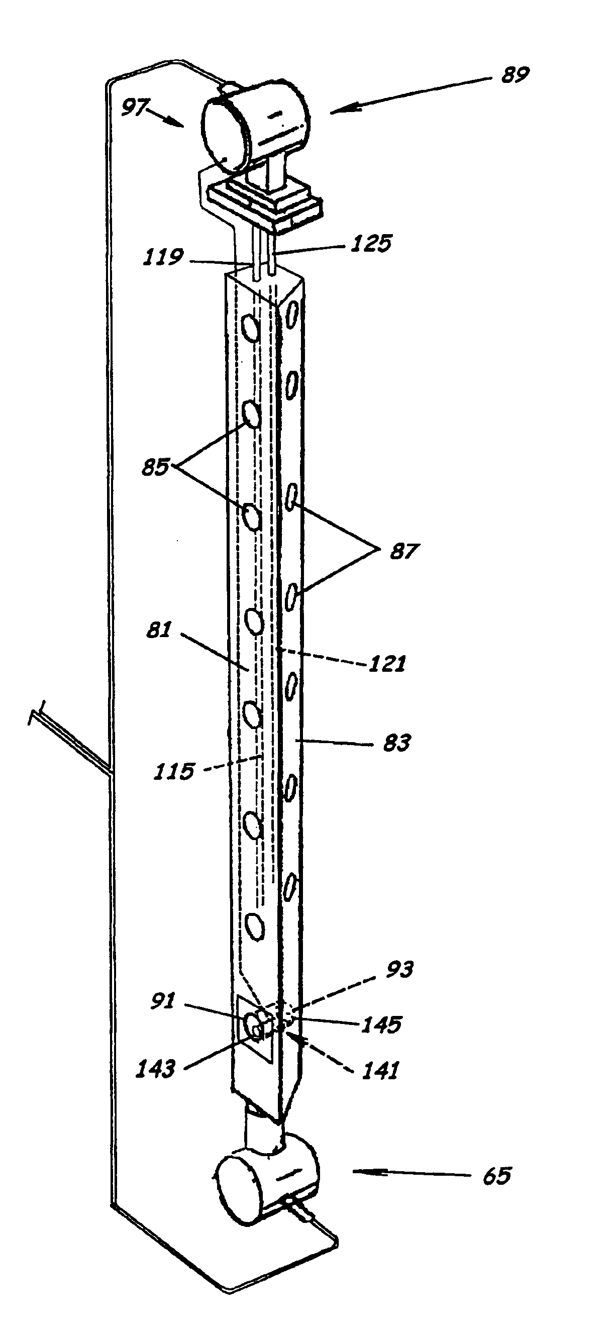
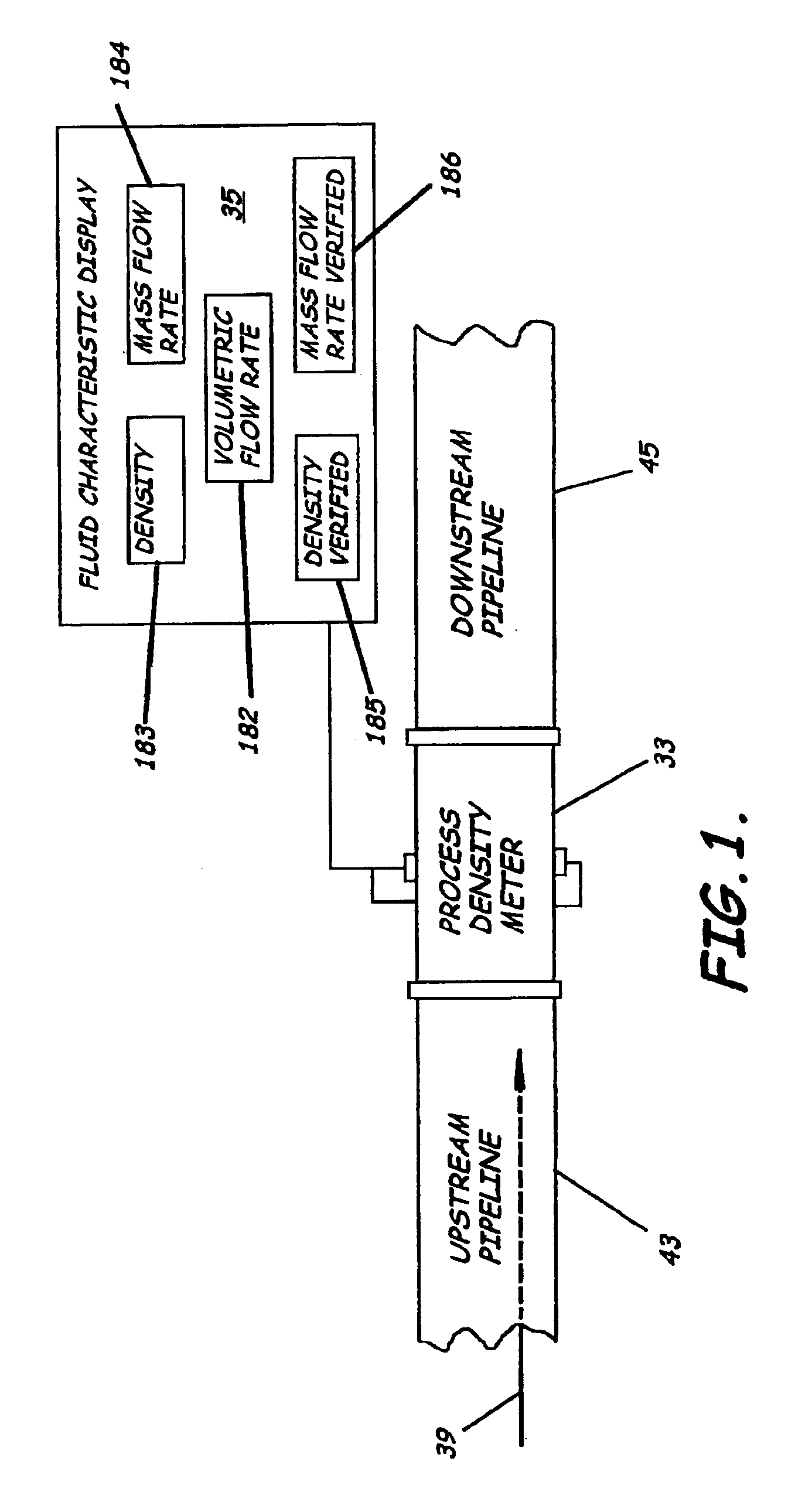
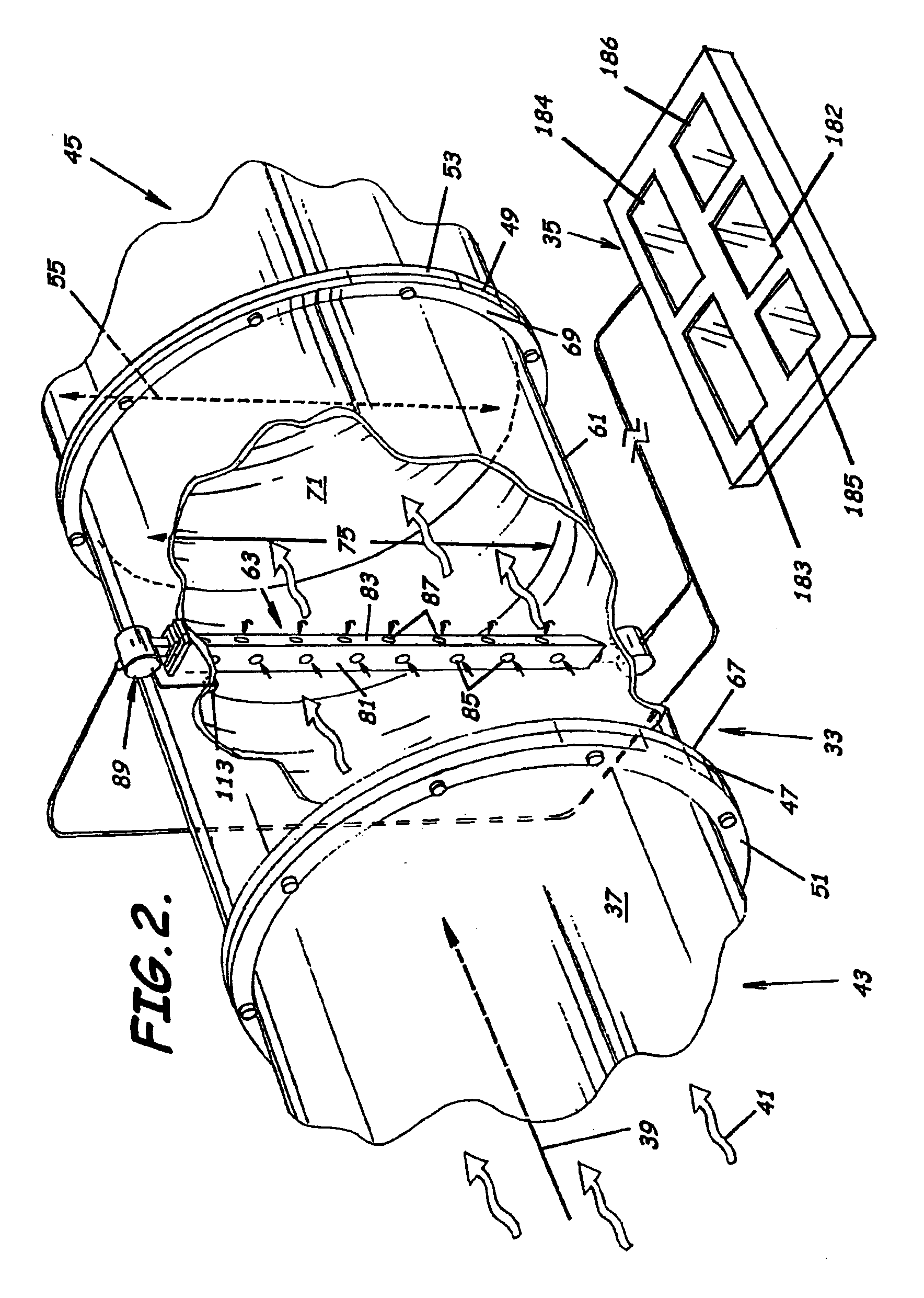
[0068]As illustrated in FIGS. 1-14, embodiments of the present invention advantageously provide a system, meter, and methods for measuring fluid flow characteristics in a pipeline. In particular, the flow characteristics of primary interest relate to industrial combus...


PUM

PropertyMeasurementUnit
temperatureaaaaaaaaaa
process densityaaaaaaaaaa

Abstract

A system to measure fluid flow characteristics in a pipeline, meter, and methods includes a pipeline having a passageway to transport flowing fluid therethrough, a process density meter including at least portions thereof positioned within the pipeline to provide flowing fluid characteristics including volumetric flow rate, fluid density, and mass flow rate of the flowing fluid, and a fluid characteristic display to display the fluid characteristics. The process density meter includes a vortex-shedding body positioned within the pipeline to form vortices and a vortex meter having a vortex frequency sensor to measure the frequency of the vortices and to determine the volumetric flow rate. The process density meter further includes a differential pressure meter positioned adjacent the vortex-shedding body to produce a differential pressure meter flow rate signal indicative of the density of fluid when flowing through the pipeline. The process density meter also includes a thermal flow meter positioned adjacent the vortex-shedding body to produce a mass flow rate signal indicative of the mass flow rate of fluid when flowing through the pipeline. The process density meter produces an output of a volumetric flow rate, a flowing fluid density, and a mass flow rate to be displayed by the fluid characteristic display.

Description

RELATED APPLICATIONS[0001]This application claims the benefit of provisional patent application No. 60 / 495,743, filed on Aug. 15, 2003.BACKGROUND OF THE INVENTION[0002]1. Field of the Invention[0003]The present invention relates generally to flow meters. In more specific aspects, the present invention relates to the measurement of the density, specific gravity, and flow rate of flowing fluids, systems, apparatus and methods.[0004]2. Description of the Related Art[0005]Many industrial facilities feed fuel gases to their industrial combustion processes. Particularly, these fuel gases tend to be low molecular weight hydrocarbon fuel gases. These fuel gases typically have a constantly changing hydrocarbon composition. To maintain an efficient fuel-air ratio combustion control, the BTU content, must be known. The BTU content of the fuel gas can be determined directly via a BTU analysis or the BTU content can be inferred from the fuel gas density or specific gravity. Both direct BTU measu...

Claims


Application Information

Patent Timeline
Patent Type & Authority Patents(United States)
IPC IPC(8): G01F1/32G01F1/86G01F1/76G01N9/00
CPCG01F1/3209G01F1/3254G01F1/3272G01F1/86G01N9/00G01F1/3273G01F1/3259
Inventor SPRAGUE, JAMES L.
Owner SAUDI ARABIAN OIL CO
Why Eureka
Try Eureka