Thin wall fitment for spouted pouch

Inactive Publication Date: 2005-10-25
ILLINOIS TOOL WORKS INC
View PDF24 Cites 49 Cited by
  • Summary
  • Abstract
  • Description
  • Claims
  • Application Information

AI Technical Summary

Benefits of technology

[0010]It is therefore an object of the present invention to provide a fitment with canoe-shaped walls whi

Problems solved by technology

That is, a canoe base which is enlarged for the above reasons requires increased dwell time and pressure to bring i

Method used


Image

  • Thin wall fitment for spouted pouch
  • Thin wall fitment for spouted pouch
  • Thin wall fitment for spouted pouch

Examples


Embodiment Construction

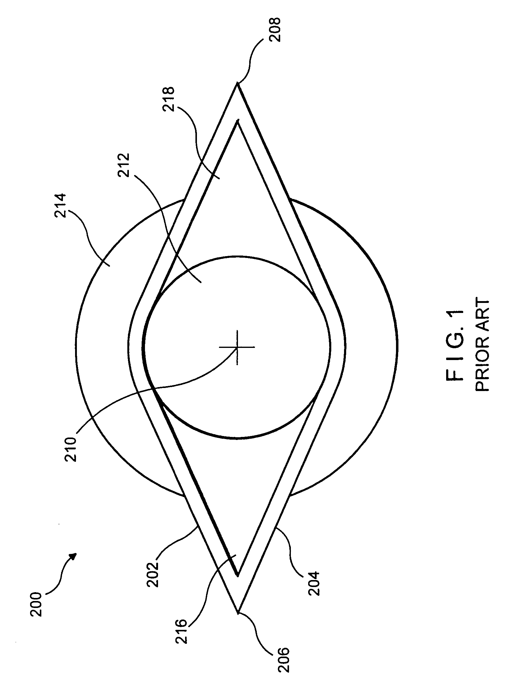
[0022]Referring now to the drawings in detail wherein like numerals refer to like elements throughout the several views, one sees that FIG. 1 is a top plan view of a prior art fitment 200. Fitment 200 includes canoe-shaped walls 202, 204 which join to form pointed ends 206, 208. The shape of walls 202, 204 and pointed ends 206, 208 allows for a gradual transition from the two plies of film (not shown, but which are sealed to walls 202, 204) to the maximum width of the canoe in the diametrical center 210 of the fitment 200, wherein spout aperture 212 is formed. Spout aperture 212 passes through a stem (not shown) which typically includes an externally threaded structure and a cylindrical flange 214 and further forms spout walls to allow the dispensing of liquid or near-liquid product from a container formed by two plastic sheets sealed to walls 202, 204. While not shown in FIG. 1, walls 202, 204 may include a ribbed structure, with ribs extending from pointed end 206 to pointed end 2...


PUM

PropertyMeasurementUnit
Temperatureaaaaaaaaaa
Thicknessaaaaaaaaaa
Thicknessaaaaaaaaaa

Abstract

A fitment has walls with a spout aperture therebetween. Reduced wall thickness results in a reduced amount of plastic in the fitment. An alternative embodiment uses radially extending meltable fins. During installation in a sealing apparatus, a heated mandrel engages the inner diameter of the spout aperture thereby pre-heating and physically supporting the fitment during the installation process. The heated mandrel typically engages the fitment at least one cycle prior to be installed. The fitment may be canoe-shaped.

Description

CROSS-REFERENCE TO RELATED APPLICATION[0001]This application is a divisional of U.S. patent application Ser. No. 09 / 643,033, filed on Aug. 21, 2000, no U.S. Pat. No. 6,612,466, issued on Sep. 2, 2003 the disclosure of which is incorporated herein by reference.BACKGROUND OF THE INVENTION[0002]1. Field of the Invention[0003]This invention pertains to a fitment for a spouted pouch, particularly one with a canoe-type base or meltable fin wherein the plastic is reduced in transition areas and in the wall thickness of the base. To accelerate and maintain the integrity of the process for installing a fitment, a heated mandrel shaped and sized to the inner diameter of the fitment passageway is used.[0004]2. Description of the Prior Art[0005]In the prior art, it is known to use a fitment / spout with a canoe shaped base with extended meltable fins oriented 180° apart, and multiple horizontal ribs spaced evenly across the height of the canoe. The canoe shape and the meltable fins assure gradual...

Claims


Application Information

Patent Timeline
IPC IPC(8): B29C65/00B29C65/18B65D75/58B65D75/52B65D83/00B31B1/84B31B19/84B65D33/38
CPCB29C65/18B29C66/30223B29C66/53262B29C66/53263B29C66/63B65D75/5883B29C65/305B65D2575/583B29L2031/7128B29C66/232B29C66/0242B29C66/1122B29C66/242B29C66/112B29C66/114B29C66/8322B65D33/00
Inventor MALIN, ART
Owner ILLINOIS TOOL WORKS INC
Why Eureka
Try Eureka