Eureka AIR delivers breakthrough ideas for toughest innovation challenges, trusted by R&D personnel around the world.

Microbolometer detector with high fill factor and transducers having enhanced thermal isolation

Active Publication Date: 2005-10-25
TELEDYNE FLIR LLC +1
View PDF16 Cites 5 Cited by
  • Summary
  • Abstract
  • Description
  • Claims
  • Application Information

AI Technical Summary

Benefits of technology

[0005]In accordance with this invention, each transducer unit is supported by at least two leg members that are attached to the underlying ROIC chip at locations beneath other transducer members. This eliminates the necessity of fabricating serpentine or other complicated configurations in order to increase the effective length of the leg members and thereby increase the thermal isolation of the transducer units. Moreover, the length of the leg members is not limited by the area underneath a single transducer unit.
[0006]A variety of embodiments may be fabricated in accordance with this invention. The leg members may extend from locations underneath transducer units of opposite sides of the supported transducer unit. The leg members need not be attached to the ROIC chip at locations underneath adjacent transducer units but instead may originate at locations underneath transducer units that are further removed from the supported transducer unit. The leg members need not originate from locations on opposite sides of the supported transducer unit but may originate from locations underneath a transducer unit on the same side of the supported transducer unit, from locations underneath transducer units located at a right angle in relation to the supported transducer unit, etc. The leg members do not have to be straight but may contain transverse sections, serpentine configurations or other geometric patterns to increase the effect length of the leg members.

Problems solved by technology

The fabrication of these serpentine structures, however, may require relatively dense photolithographic processing.
This processing density may result in low yields.
In addition, the effective length of the leg members, even when they are formed in a serpentine configuration, is limited by the area underneath the transducer.

Method used


Image

  • Microbolometer detector with high fill factor and transducers having enhanced thermal isolation
  • Microbolometer detector with high fill factor and transducers having enhanced thermal isolation
  • Microbolometer detector with high fill factor and transducers having enhanced thermal isolation

Examples


Embodiment Construction

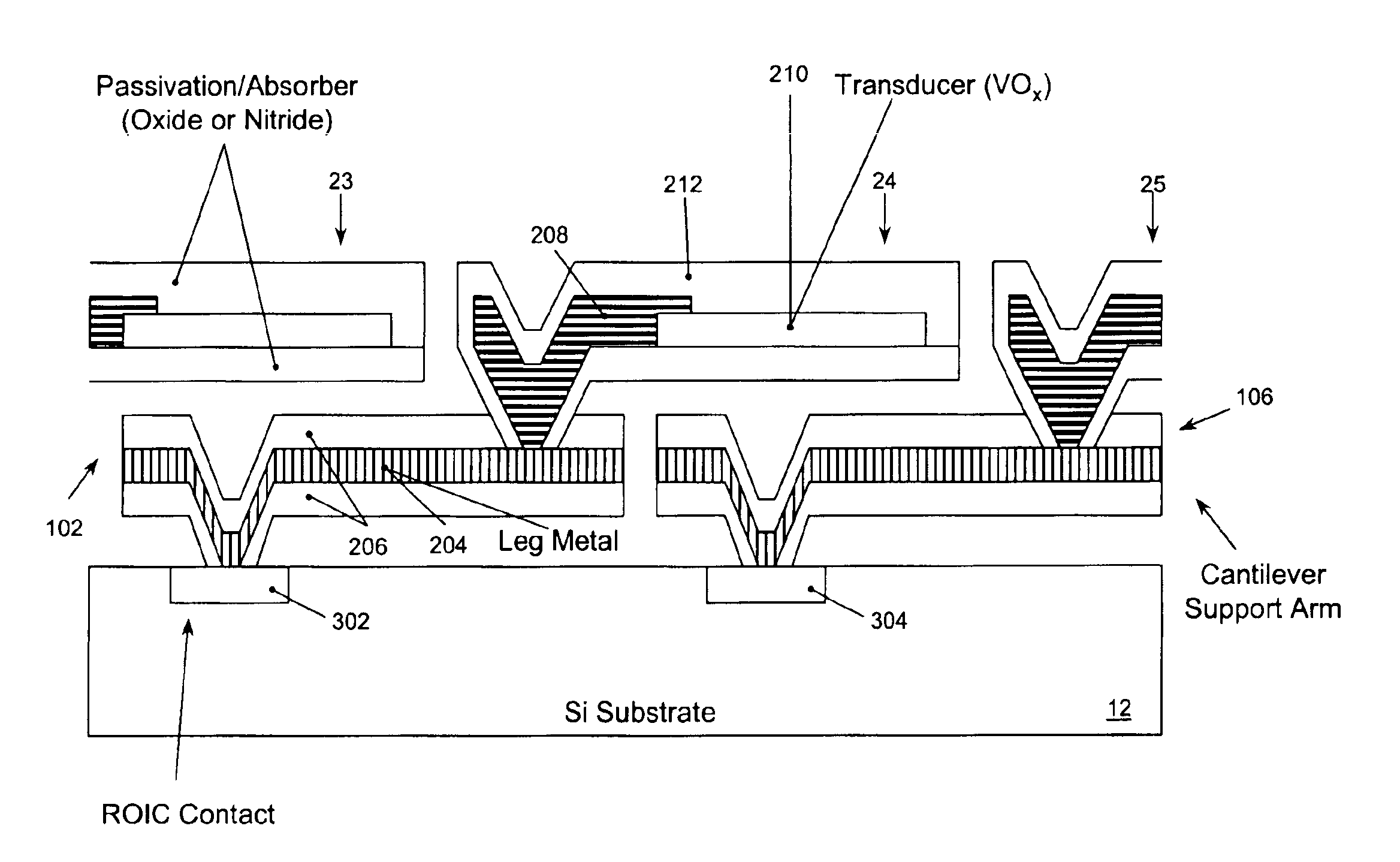
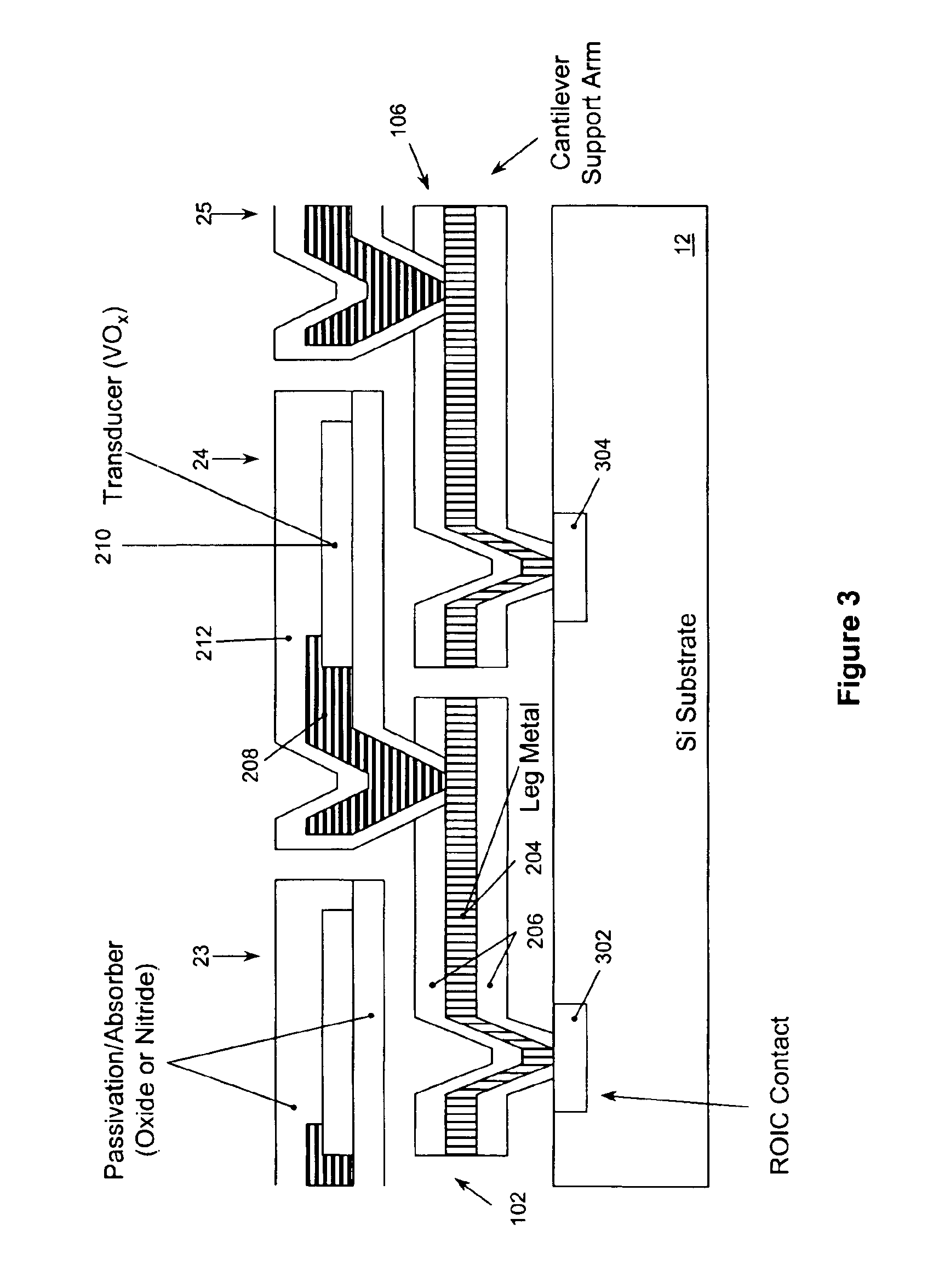
[0014]In arrangements according to this invention, the leg members that constitute the support structure for the transducer units extend under neighboring transducer units. Many alternative embodiments are possible.

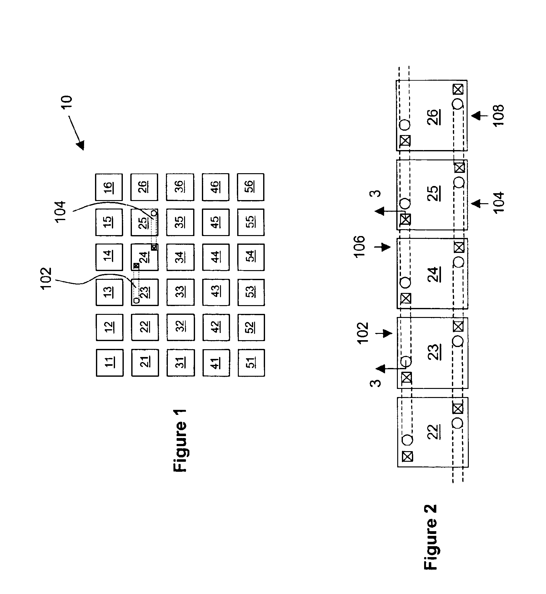
[0015]FIG. 1 is a top view of a focal plane array 10 which includes transducer units 11-16, 21-26, 31-36, 41-46 and 51-56. Focal plane array 10 is rectangular, although in other embodiments other geometries could be used. The separation between the transducer units is exaggerated for purposes of illustration. In reality, the transducer units could be closer together. Transducer unit 24 is shown as supported by a support structure that includes leg members 102 and 104. Leg member 102 extends from a location on the ROIC chip (not shown) beneath transducer unit 23 to a point of attachment on the transducer unit 24. Leg member 104 extends from a location on the ROIC chip beneath transducer unit 25 to a point of attachment on the transducer unit 24. (Note: In the drawings, the...


PUM


Abstract

In a microbolometer detector the individual transducers in the focal plane array are support by leg members that are attached to the underlying readout integrated circuit (ROIC) chip at locations underneath transducers other than transducer which they support. A variety of configurations are possible. For example, the leg members may be attached to the ROIC chip at locations under adjacent transducers on opposite sides or on the same side of the supported transducer, or at locations underneath transducers that are not immediately adjacent to the supported transducer. In this way the effective length of the leg members and therefore the thermal isolation of the transducer they support can be increased.

Description

FIELD OF THE INVENTION[0001]This invention relates to microbolometer detectors and in particular to a microbolometer detector for detecting infrared radiation wherein the transducer elements are highly thermally isolated from the readout integrated circuit chip.BACKGROUND OF THE INVENTION[0002]The general structure of microbolometer detectors is well known in the art. Briefly, they include a two-dimensional array of transducers, each of which is electrically connected to an underlying readout integrated circuit (ROIC) chip that contains circuitry for detecting changes in the resistance of the transducer. The array is often referred to as a “focal plane array” and the individual detectors are referred to as “pixels”. The transducers are formed of a material, such as vanadium oxide, which has a high thermal coefficient of resistance (TCR). To isolate the transducers thermally, they are typically held by a structure that supports them in a suspended position over the ROIC chip. When ra...

Claims


Application Information

Patent Timeline
IPC IPC(8): G01J5/20
CPCG01J5/20
Inventor TERRE, WILLIAM A.WOOLAWAY, JAMES T.JEROMINEK, HUBERTALAIN, CHRISTINE
Owner TELEDYNE FLIR LLC
Why Eureka
Eureka Blog
Learn More