Voltage generating apparatus with a fine-tune current module

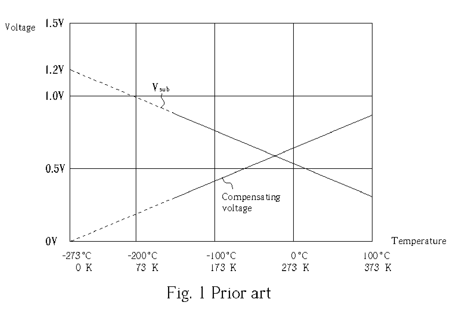
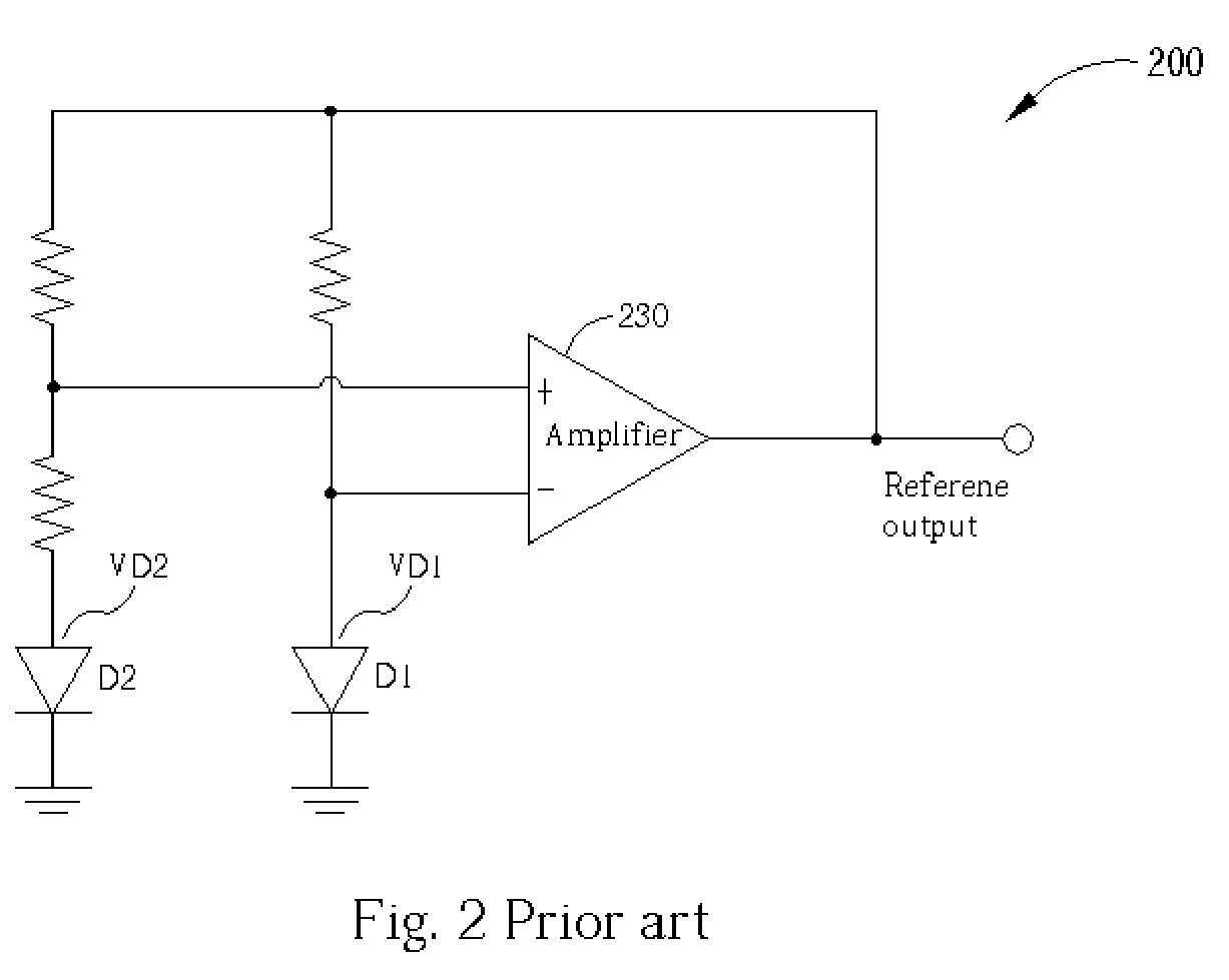
a voltage generating apparatus and fine-tune technology, applied in the direction of instruments, vehicle components, power supply lines, etc., can solve the problems of bjts' reference voltage generator in fig. 1, the actual voltage output of the circuit will deviate from the design value, and the band gap of silicon is about 1.2v to 1.3v,

Active Publication Date: 2005-10-25
EMEMORY TECH INC
View PDF3 Cites 44 Cited by
  • Summary
  • Abstract
  • Description
  • Claims
  • Application Information

AI Technical Summary

Benefits of technology

[0012]According to the claimed invention, a voltage generator comprises a positive temperature coefficient current generating module, wherein an output current of the positive temperature coefficient current generating module increases with a rising ambient temperature; a negative temperature coefficient current generating module, wherein an output current of the positive temperature coefficient current generating module decreases with rising ambient temperature; a current fine-tune module used for adjusting the output current of the negative temperature coefficient current generating module; and a voltage output module, connected to the positive temperature coefficient current generating module and the negative temperature coefficient current generating module for generating an output voltage according to the positive temperature coefficient current generating module and the negative temperature coefficient current generating module.

Problems solved by technology

Thus, the reference voltage generator in FIG. 1 implemented by BJTs has the disadvantage of higher price compared to some products.
Moreover, the bandgap of silicon, being about 1.2V to 1.3V, cannot satisfy future trends in low power applications.
However, the prior art in FIG. 3 has the disadvantage that although the generated voltage is stable with respect to temperature variation, the actual voltage output of the circuit will deviate from the design value due to processing variation.

Method used


Image

  • Voltage generating apparatus with a fine-tune current module
  • Voltage generating apparatus with a fine-tune current module
  • Voltage generating apparatus with a fine-tune current module

Examples


Embodiment Construction

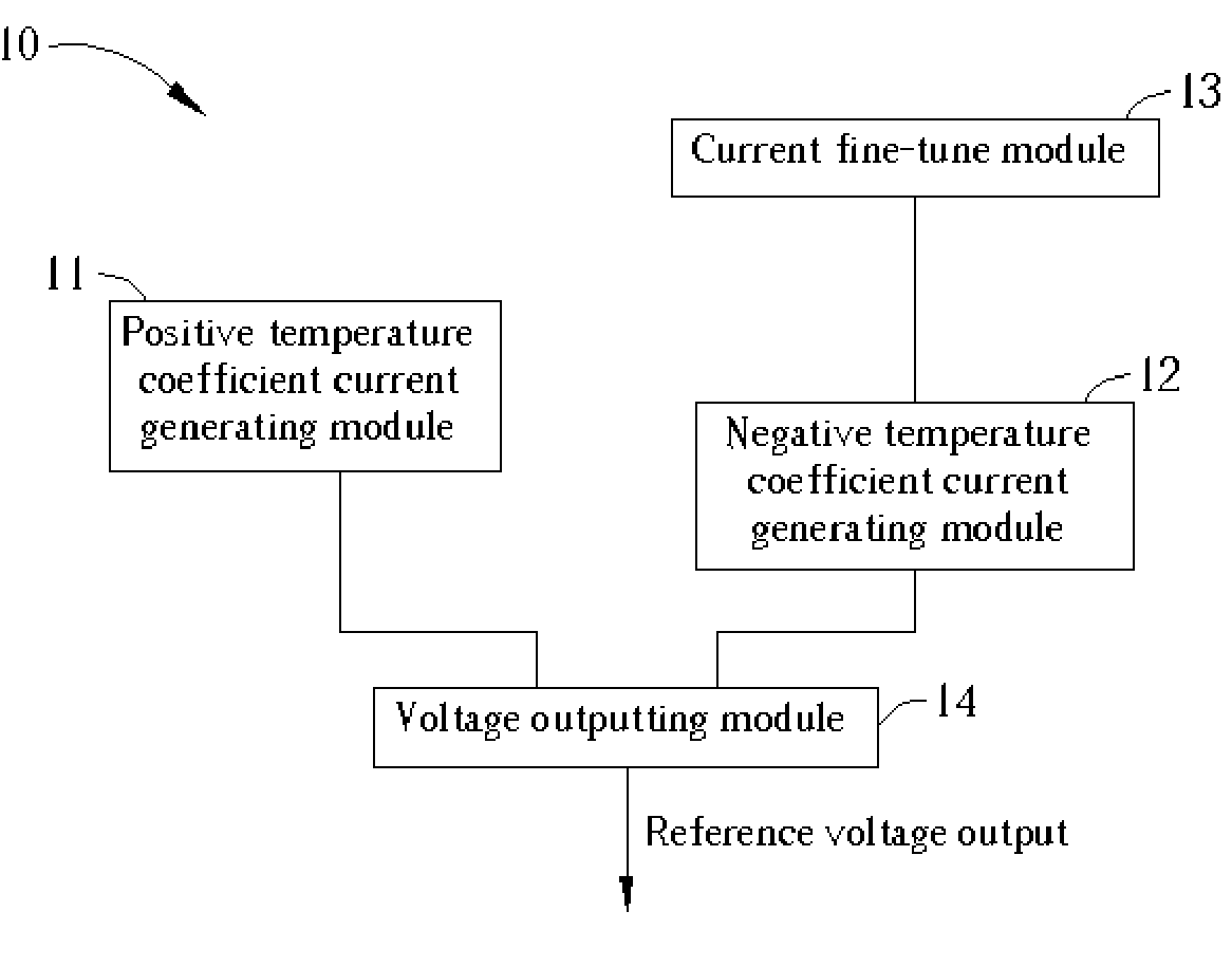
[0032]Please refer to FIG. 4. FIG. 4 illustrates function blocks of a voltage generator 10 according to the present invention. The voltage generator 10 comprises a positive temperature coefficient current generating module 11, a negative temperature coefficient current generating module 12, a current fine-tune module 13, and a voltage output module 14. The positive temperature coefficient current generating module 11 is used to generate a current of a positive temperature coefficient (a current of a positive temperature coefficient means that when the ambient temperature rises, the current will increase, wherein the increasing slope of the current is the positive temperature coefficient). The negative temperature coefficient current generating module 12 is used to generate a current of negative temperature coefficient (Similarly, a current of a negative temperature coefficient means that when the ambient temperature rises, the current will decrease, wherein the decreasing slope of t...


PUM


Abstract

Voltage generating apparatus includes a positive temperature coefficient current generating module, a negative temperature coefficient current generating module, a fine-tune current module and a voltage output module. The function of the positive temperature coefficient current generating module and the negative temperature coefficient current generating module, which take advantage of characteristics of MOS devices operated in the sub-threshold region, is to generate a stable current of positive temperature coefficient and a stable current of negative temperature coefficient, respectively. The current fine-tune module increases or decreases output current of the negative temperature coefficient current generating module. The voltage output module sums two output currents of the positive temperature coefficient current generating module and the negative temperature coefficient current generating module and transforms the total current into output voltage that is stable under temperature and process variation.

Description

BACKGROUND OF INVENTION[0001]1. Field of the Invention[0002]The present invention relates to a voltage generating apparatus, more particularly, to a voltage generating apparatus with a fine-tune current module.[0003]2. Description of the Prior Art[0004]Almost all analog or mixed-mode circuits need reference voltages to provide the bias voltage. The reference voltage can generate a constant and reproducible voltage even during process variation, change of ambient temperature, and supply voltage instability so that the circuits can operate with accurate DC bias. Therefore, a DC voltage generator is an important block in many circuits.[0005]A well-known method of generating a stable reference voltage is to utilize the phenomenon of semiconductor bandgap in a reference circuit. The bandgap energy of a semiconductor will change predictably with ambient temperature, and bandgap reference circuits are designed according to this principle. The most popular method of generating bandgap volta...

Claims


Application Information

Patent Timeline
Patent Type & Authority Patents(United States)
IPC IPC(8): G05F1/40G05F3/08G05F3/16G05F1/10G05F3/26G05F3/30
CPCG05F3/262G05F3/30Y10S323/907
Inventor LIN, HONG-CHINHUANG, PO-HSUANHO, CHIEN-HUNG
Owner EMEMORY TECH INC
Why Eureka
Try Eureka