

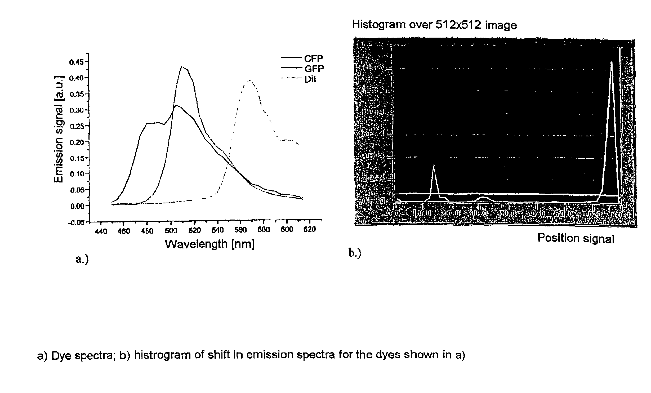
Method for the detection of dyes in fluorescence microscopy
a fluorescence microscopy and dye technology, applied in the field of fluorescence correlation spectroscopy, laser scanning microscopy, and nearfield scanning microscopy, can solve the problem that the data acquisition rate may not be worsened
- Summary
- Abstract
- Description
- Claims
- Application Information
AI Technical Summary
Benefits of technology
Problems solved by technology
Method used
Image

Examples
Embodiment Construction
[0048]The method for flexible detection is based on a spectrally split detection of fluorescence. For this purpose, the emission light is split from the excitation light in the scan module or in the microscope (with multiphoton absorption) by means of the main color splitter (MDB). A block diagram of the detector unit to be described is shown in FIG. 5. With confocal detection, the light from the specimen is focused through a diaphragm (pinhole) PH by means of imaging optics PO, so that fluorescence occurring outside of the focus is suppressed. In non-descanned detection, the diaphragm is omitted. The light is now divided into its spectral components by means of an angle-dispersive element DI. The angle-dispersive elements can be prisms, gratings and acousto-optic elements. The light which is split into its spectral components by the dispersive element is subsequently imaged on a line detector DE. This line detector DE measures the emission signal depending on the wavelength and con...
PUM
 Abstract
Description
Claims
Application Information