

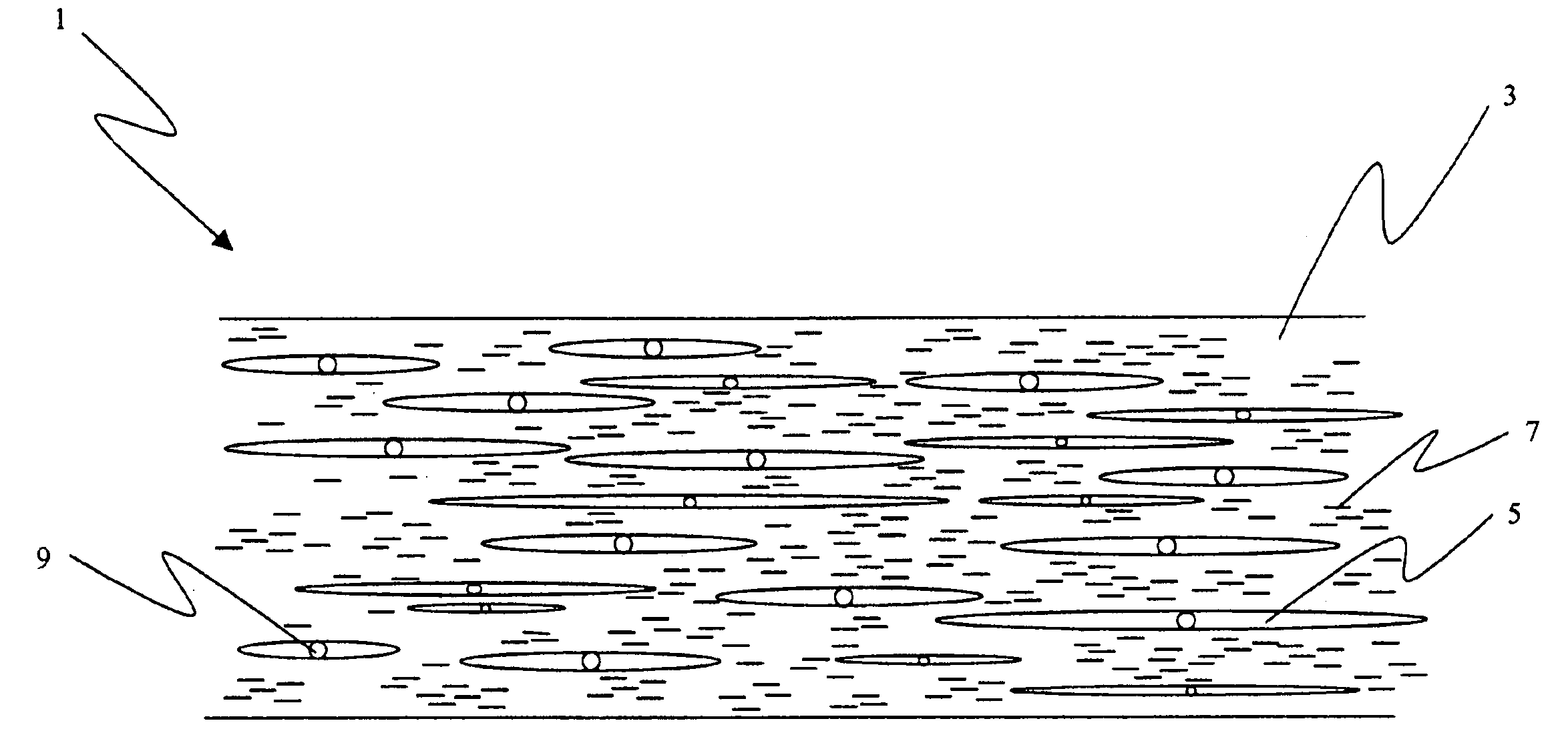
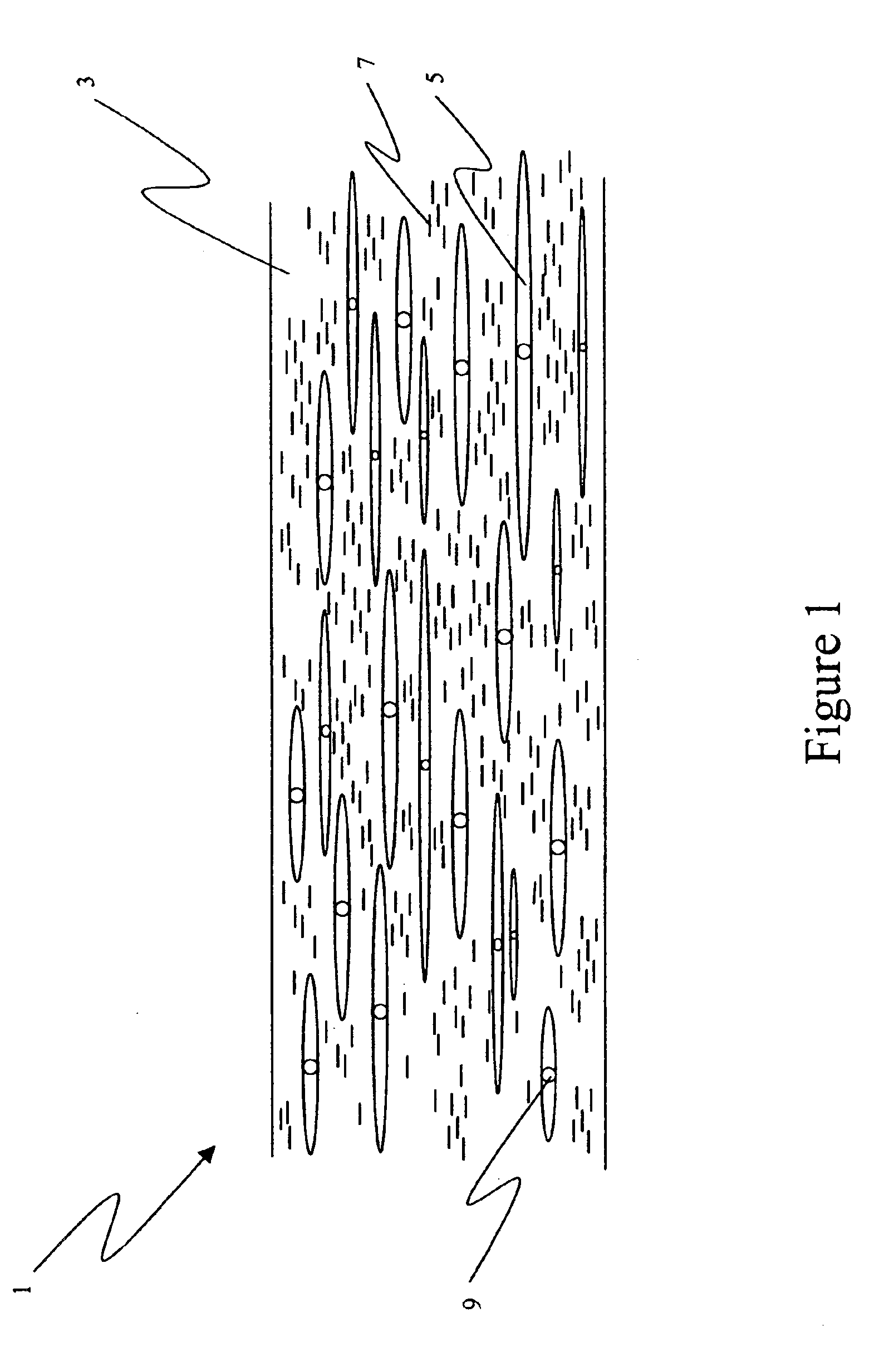
Voided polymer film containing layered particulates
a polymer film and particulate technology, applied in the field of optical light diffusing elements, can solve the problems of air contact, low efficiency, and low efficiency of prior art light diffusing devices, and achieve the effect of improving light transmission
- Summary
- Abstract
- Description
- Claims
- Application Information
AI Technical Summary
Benefits of technology
Problems solved by technology
Method used
Image

Examples
examples
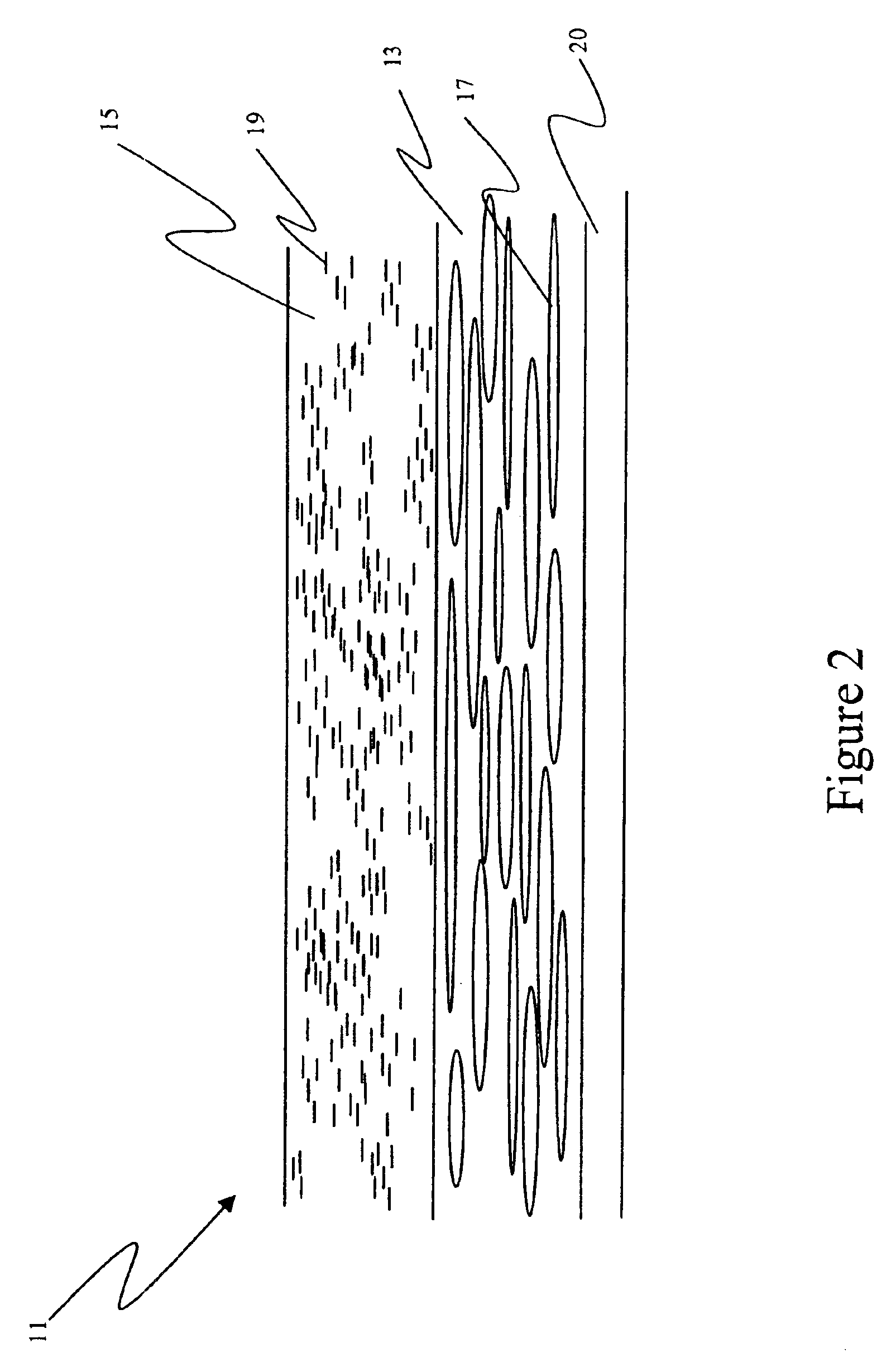
[0163]In this example, the optical element of the invention utilized co-extrusion to create a clay-containing and microvoided light diffuser suitable for diffusion of fluorescent backlighting sources typical for LCD. This diffuser was compared to single diffusion films of the same composition being either clay-containing or microvoided. This example will show that the co-extrusion of clay and microvoided polymer is advantaged to a monolayer of diffusion material, clay-containing or microvoided because it unexpectedly had higher transmission and haze than the two single films tested together. Further, it will be obvious that the diffuser film will be low in cost and have mechanical properties that allow for use in display systems.
[0164]For this example, the light diffusing films (both invention and control materials) were measured with the Hitachi U4001 UV / Vis / NIR spectrophotometer equipped with an integrating sphere. The total transmittance spectra were measured by placing the sampl...
PUM
| Property | Measurement | Unit |
|---|---|---|
| haze | aaaaa | aaaaa |
| elastic modulus | aaaaa | aaaaa |
| refractive index | aaaaa | aaaaa |
Abstract
Description
Claims
Application Information