Hole forming system with ganged spindle set

a technology of ganged spindle and hole forming system, which is applied in the direction of metal-working holders, large fixed members, supporters, etc., can solve the problems of reducing the production cost affecting the production efficiency of the whole production cost, and requiring the drilling of holes in the boards. achieve the effect of high throughpu

Inactive Publication Date: 2005-11-01
THE GSI GRP LLC
View PDF38 Cites 3 Cited by
  • Summary
  • Abstract
  • Description
  • Claims
  • Application Information

AI Technical Summary

Benefits of technology

[0010]A high throughput hole forming system with multiple spindles per spindle station is described. The system includes a base table and a work piece table for supporting work pieces under process. A first drive system moves the work piece table along a Y axis in relation to the base table. The system includes a plurality of spindle stations, each for processing at least one work piece. A plurality of sets of spindles are provided, each spindle for holding a hole forming tool. Each set includes a spindle at each spind

Problems solved by technology

Of course, printed circuit board populated with other types of devices also need holes formed in the boards.
There has been a dramatic increase in the hole count on printed circuit boards, which makes the cost of drilling the holes a significant part of the total production cost.
In addition, hole sizes are getting smaller.
Small drills are more expensive and can not be fed w

Method used


Image

  • Hole forming system with ganged spindle set
  • Hole forming system with ganged spindle set
  • Hole forming system with ganged spindle set

Examples


Embodiment Construction

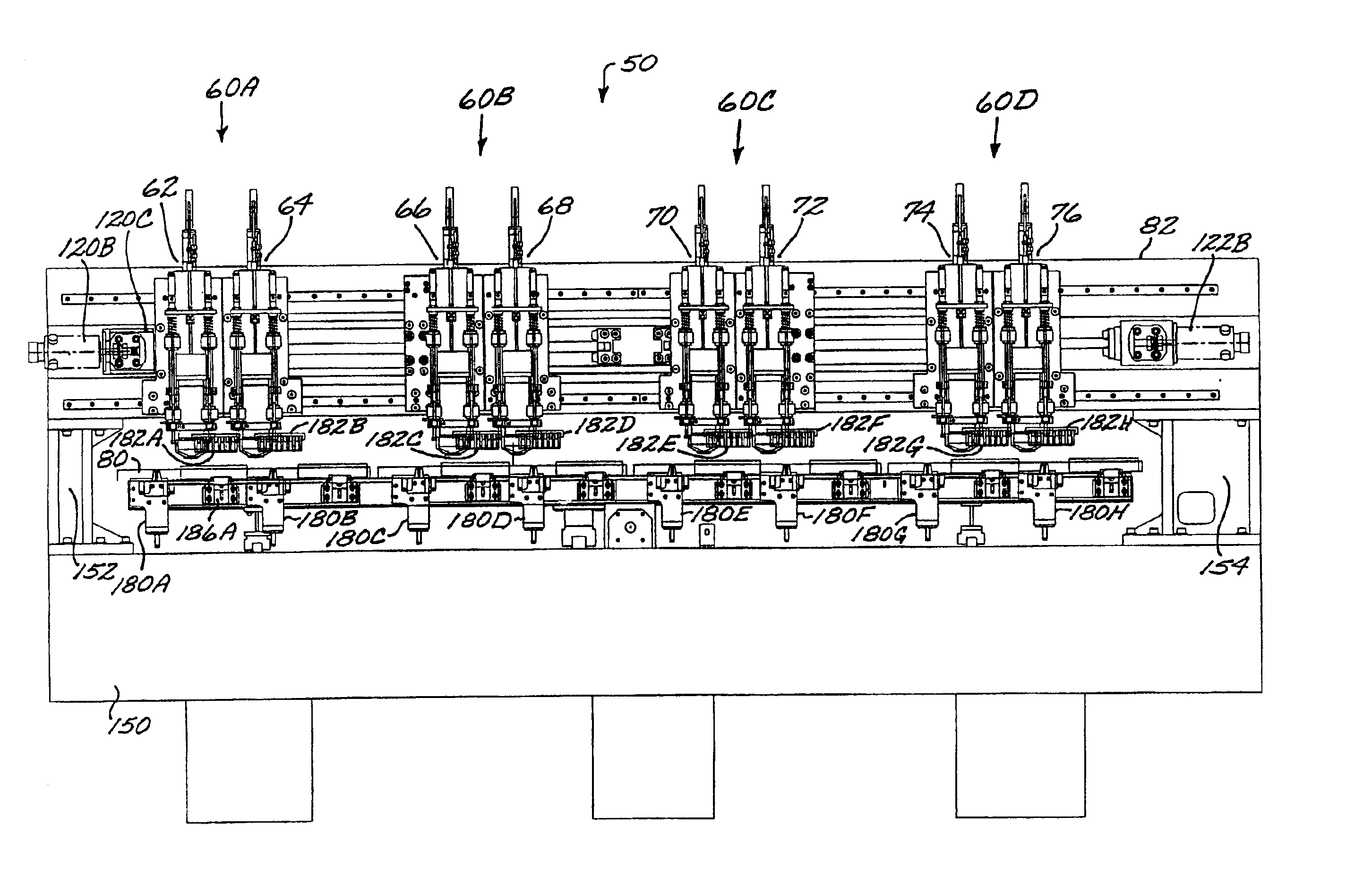
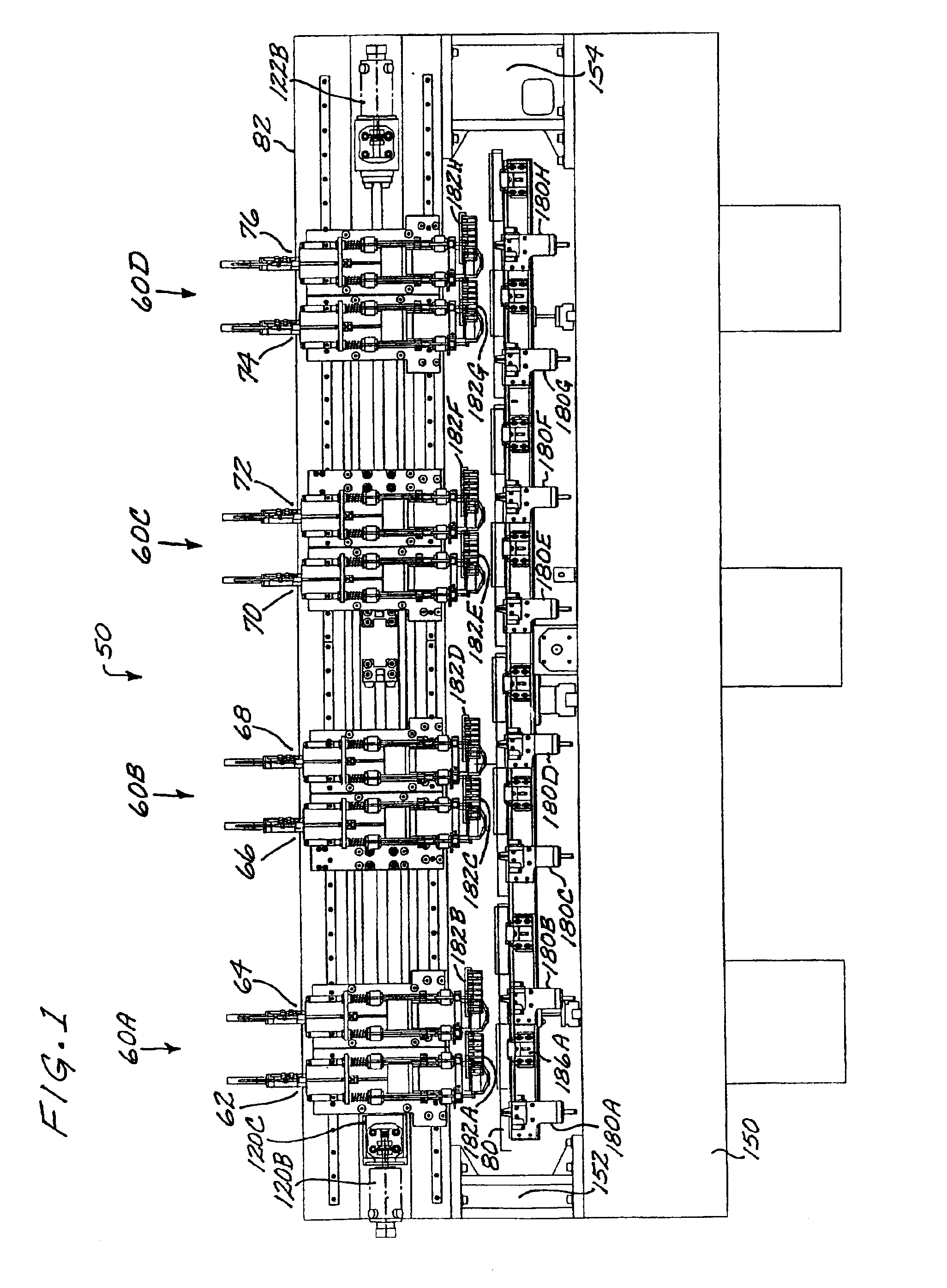
[0031]In accordance with one aspect of the invention, a multiple spindle per station drilling system is described. An exemplary embodiment is illustrated in FIG. 1 as drilling system 50, and provided two spindles per station. Using two spindles per station produces a large gain in productivity over conventional systems, since the same number of holes can be produced in half the time, assuming that multiple images are used in producing the board. Multiple images on a board represents the norm, not the exception, in today's production of printed circuit boards. Therefore, adding a second spindle to each station will contribute significantly to machine productivity. There are additional benefits to utilizing this type of new system architecture. For example, the number of tool change cycles can be reduced by 50%, because the two spindles are changing drills at the same time.

[0032]This invention is not limited to applications employing two spindles per spindle station, as it is contempl...


PUM

PropertyMeasurementUnit
Forceaaaaaaaaaa
Sliding frictionaaaaaaaaaa

Abstract

A high throughput drilling system for printed circuit board hole formation. Two spindles are disposed at each spindle station, doubling the number of holes produced in a given time period. Each spindle in connected to an overhead linear drive by a mini slide. A first set of the spindles, one for each spindle station, is driven by a first X axis linear drive. A second set is driven by a second X axis linear drive. The work piece table is elongated to support work pieces for all stations, and is supported by a set of bearing guides, with outrigger bearings coupled to the table by flexure mounts that relieve stress due to differential temperature expansion rates between the work piece table and the base table. High speed spindles are employed to obtain higher productivity, with larger holes routed by router tools, eliminating the need for stocking large drill sizes on the system tool changer.

Description

CROSS-REFERENCE TO RELATED APPLICATIONS[0001]This application is a continuation of application Ser. No. 09 / 713,689, filed Nov. 15, 2000, now U.S. Pat. No. 6,325,576, in turn a division of application Ser. No., 09 / 310,055, filed May 11, 1999, now U.S. Pat. No. 6,174,271, in turn a division of application Ser. No. 08 / 815,375, filed Mar. 9, 1997, now U.S. Pat. No. 5,920,973.TECHNICAL FIELD OF THE INVENTION[0002]This invention relates to the field of high speed drilling systems of the type used in the fabrication and population of printed circuit boards, and more particularly to a high throughput drilling system with multiple spindles per station.BACKGROUND OF THE INVENTION[0003]Printed circuit boards are typically populated with many surface-mounted circuit devices. Many small holes are formed in the boards to interconnect the layers of the circuit board. Of course, printed circuit board populated with other types of devices also need holes formed in the boards.[0004]Drilling machines ...

Claims


Application Information

Patent Timeline
IPC IPC(8): B23Q1/25B23Q1/60B23Q11/00B23Q39/00B23Q3/157B23Q5/28B23Q5/22B23Q39/02B23B39/00B23B39/16B23Q1/00H05K3/00B23Q39/04
CPCB23B39/16B23Q1/60B23Q3/15793B23Q5/28B23Q11/0003B23Q39/022B23Q39/023B23Q39/04H05K3/0047B23B39/161Y10T483/10H05K3/0097Y10S248/901Y10T408/08Y10T408/3806Y10T409/309744Y10T408/03Y10T408/91Y10T483/1736Y10T29/5107Y10T408/3809Y10T408/385Y10T408/561Y10T409/303808Y10T408/3811Y10T83/8746
Inventor KOSMOWSKI, WOJCIECH B.
Owner THE GSI GRP LLC
Why Eureka
Try Eureka