
Anode and magnetron therewith

Inactive Publication Date: 2005-11-01
LG ELECTRONICS INC
View PDF5 Cites 8 Cited by
  • Summary
  • Abstract
  • Description
  • Claims
  • Application Information

AI Technical Summary

Benefits of technology

[0024]An object of the present invention is to provide a small sized anode, and a magnetron therewith, in which an inside diameter of the anode is reduced for saving a material cost and simplifying a fabrication process.

Problems solved by technology

The related art magnetron is failed in an optimal design, with waste of material.
That is, even though cost of the magnetron can be reduced substantially if the oxygen-free copper used in the anode of the related art magnetron is reduced while maintaining performance of the magnetron, there are no researches for this.

Method used


Image

  • Anode and magnetron therewith
  • Anode and magnetron therewith
  • Anode and magnetron therewith

Examples


Embodiment Construction

[0041]Reference will now be made in detail to the preferred embodiments of the present invention, examples of which are illustrated in the accompanying drawings. In describing embodiments of the present invention, the same parts will be given the same names and reference symbols, and repetitive description of which will be omitted.

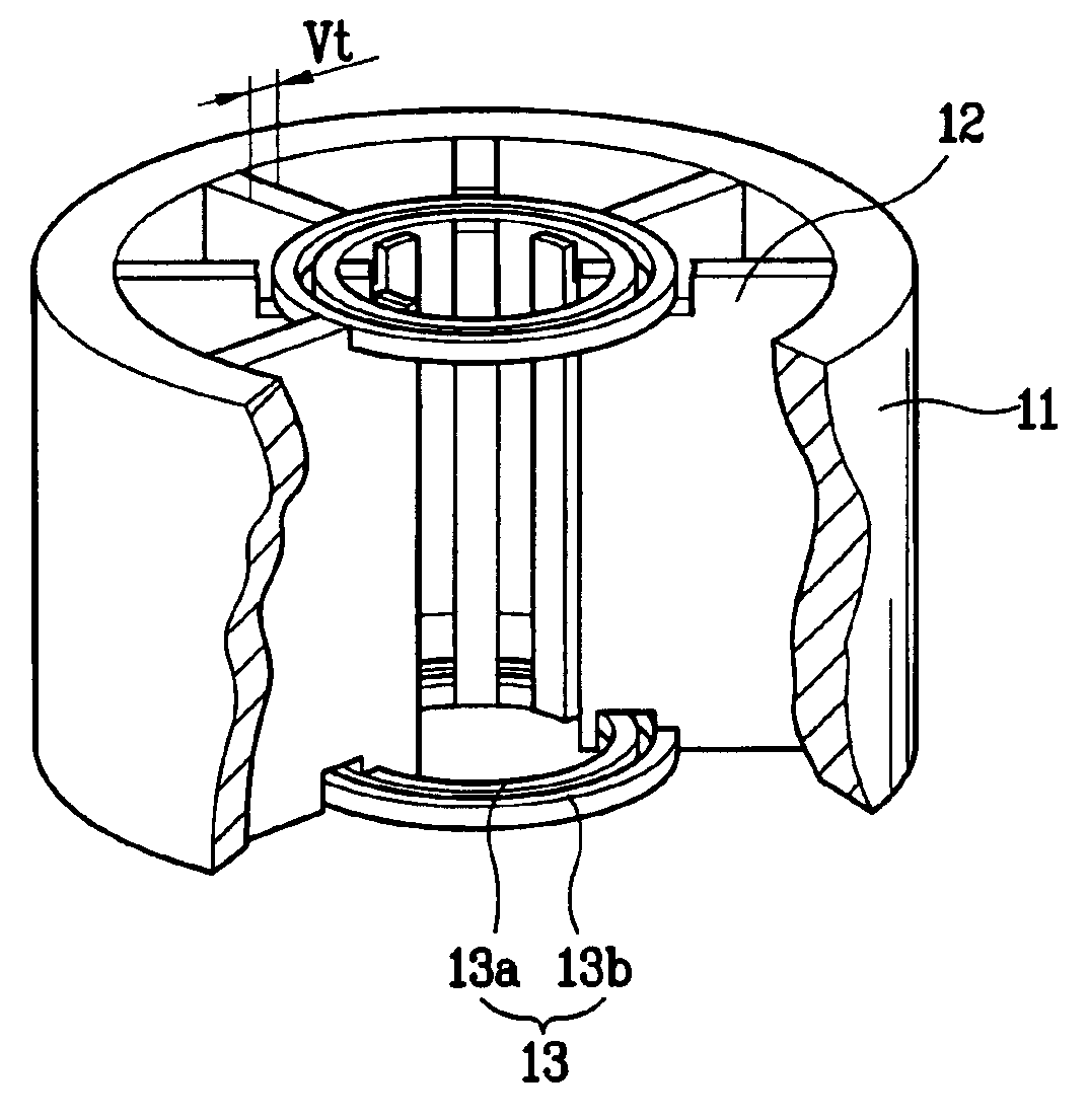
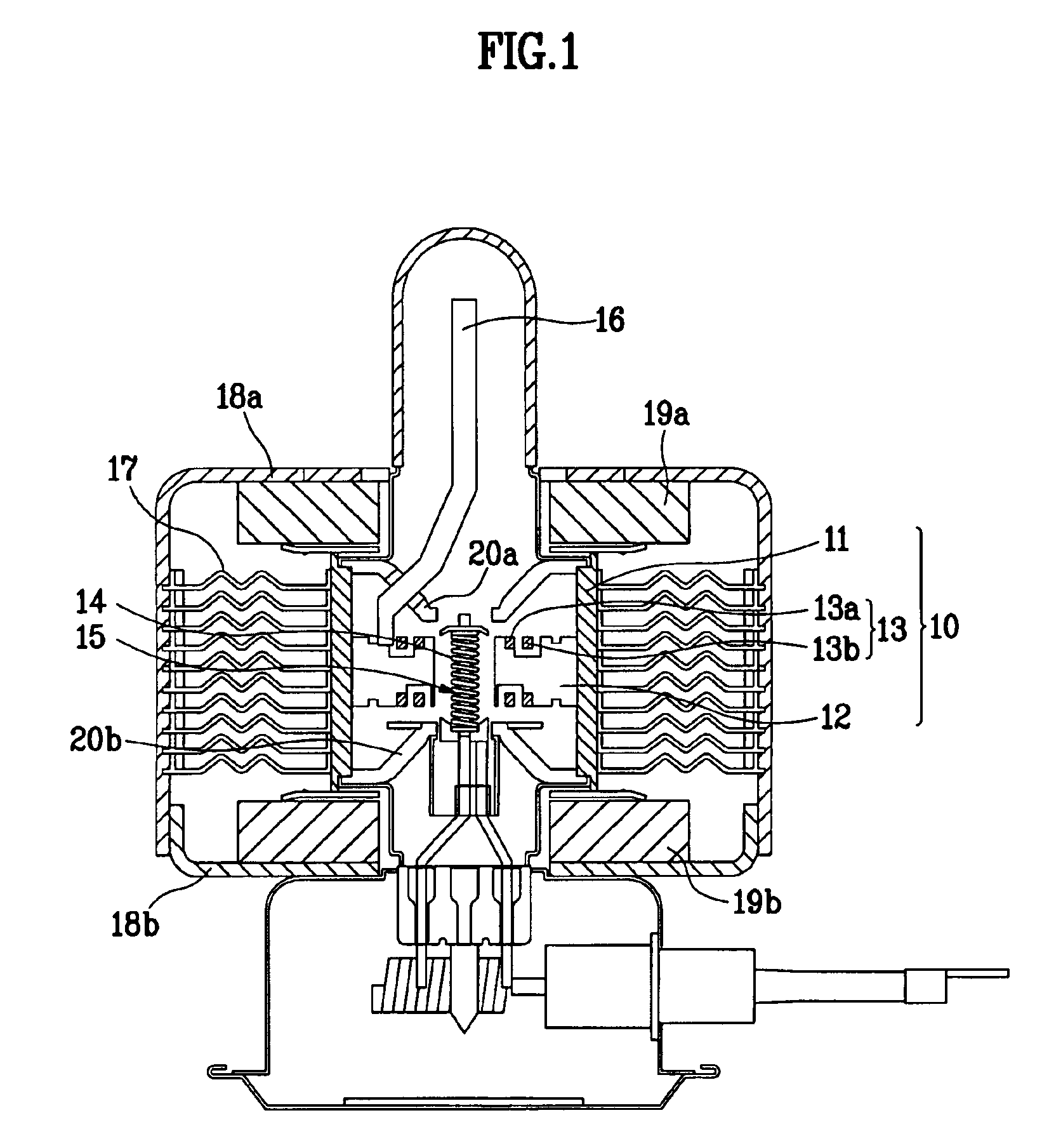
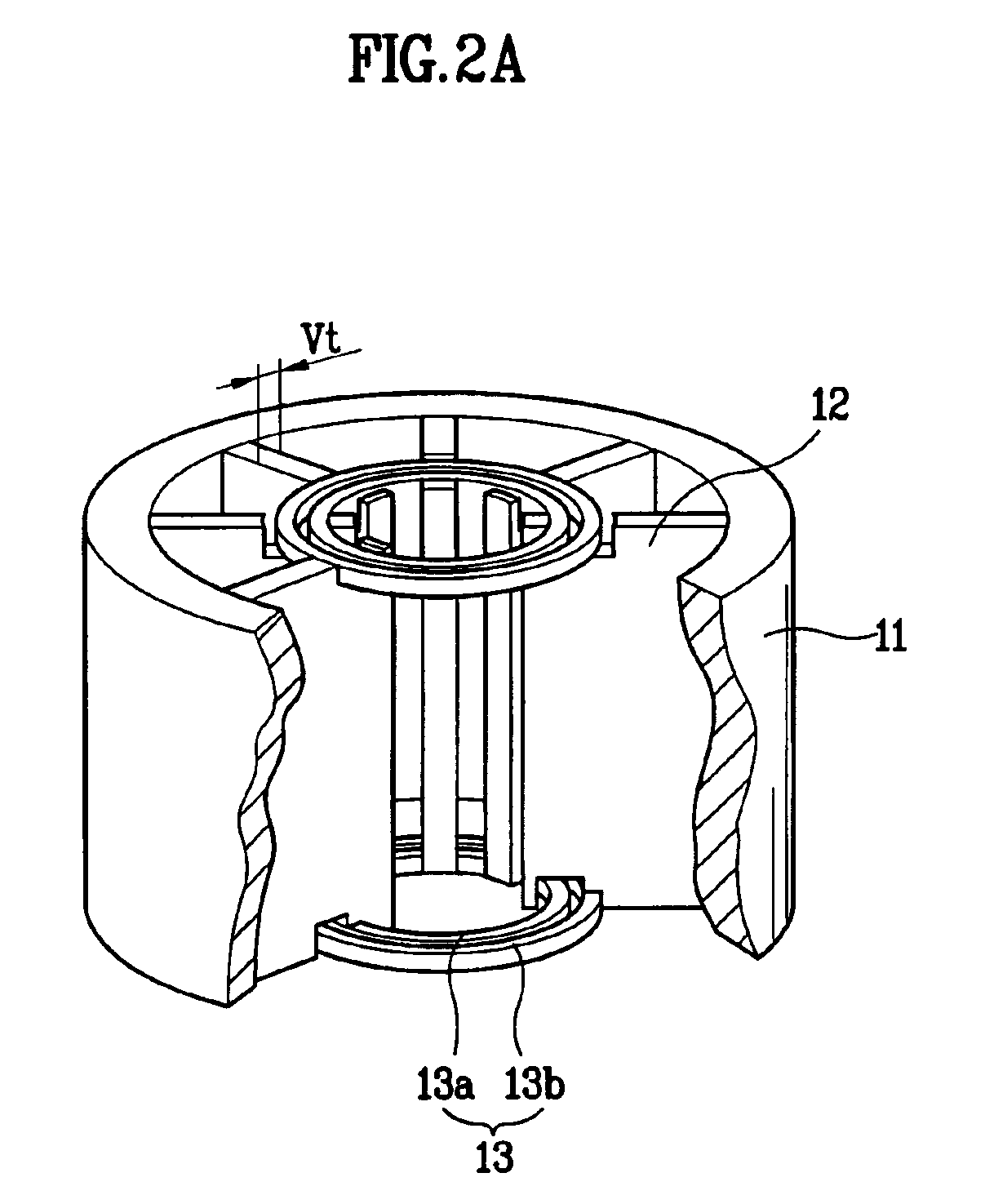
[0042]The magnetron of the present invention has an anode body 11 of which inside diameter Dbi has a value between a lowest value of 32.5 mm at which characteristics of the magnetron (the resonance frequency, thermal characteristics, and the like) can be maintained, and a highest value of 34.0 mm which meets the purpose of fabricating a small sized magnetron. Also, the magnetron of the present invention has more than 10 vanes, and an energy efficiency higher than 70%, and a 2450 MHz anode 10 resonance frequency.

[0043]The anode 10 used in the experiment has 35.5 mm inside diameter Dbi, and 10 vanes 12. The distance Da between the vanes 12 is in the range of...


PUM

PropertyMeasurementUnit
Fractionaaaaaaaaaa
Lengthaaaaaaaaaa
Lengthaaaaaaaaaa

Abstract

Anode with a 2450 MHz resonance frequency, and magnetron therewith, the anode including a cylindrical anode body with an inside diameter in a range of 32.5 to 34.0 mm, a total of ten vanes fitted to an inside circumferential surface of the anode body in a radial direction, and an inner strap and an outer strap provided to both of an upper surface and a lower surface of each vane, a distance of the inner strap and the outer strap being in a range of 0.8 to 1.2 mm, and each of the inner strap and outer strap being in contact with every second vanes for electrical connection of the vanes alternately. The anode body and the vanes are formed as one unit for simplification of a fabrication process.

Description

[0001]This application claims the benefit of the Korean Application No. P2003-0002984 filed on Jan. 16, 2003, which is hereby incorporated by reference.BACKGROUND OF THE INVENTION[0002]1. Field of the Invention[0003]The present invention relates to a small sized anode, and a magnetron therewith.[0004]2. Background of the Related Art[0005]In general, the magnetrons, as a kind of vacuum tube, have applications to micro-ovens, plasma lighting apparatuses, dryers, and other high frequency systems owing to merits of simple structure, high efficiency, and stable operation, and the like.[0006]Upon application of a power to the magnetron, thermal electrons are emitted from a cathode, and the thermal electrons generate microwaves by action of a strong electric field, and a strong magnetic field applied between the cathode and an anode. The microwave generated thus is transmitted from an antenna, and used as heat source for heating an object.[0007]A system of the magnetron will be described b...

Claims


Application Information

Patent Timeline
IPC IPC(8): C23C14/35C23C14/34H01J25/587H01J23/20H01J23/02H01J23/027H01J25/00H01J25/50H01J23/16H01J23/18H01J23/15H01J23/22
CPCH01J23/18H01J23/22H01J25/587H01J23/15
Inventor LEE, YONG SOOLEE, JONG SOO
Owner LG ELECTRONICS INC
Learn More