Phase conjugate relay mirror apparatus for high energy laser system and method

a mirror apparatus and laser technology, applied in the direction of laser details, directed energy weapons, weapons, etc., can solve the problems of putting the air crew in harm's way, and achieve the effects of improving the atmospheric transmission path, high power consumption, and high thermal load

Inactive Publication Date: 2005-11-01
RAYTHEON CO
View PDF11 Cites 19 Cited by
  • Summary
  • Abstract
  • Description
  • Claims
  • Application Information

AI Technical Summary

Benefits of technology

[0008]The need in the art is addressed by the system for directing electromagnetic energy of the present invention. The invention addresses the problem of placing a large, high power consumption, high thermal load high-energy laser (HEL) system on an airborne platform. For surface ship self protection, an airborne platform is advantageous for several reasons: (1) it provides a better atmospheric transmission path (lower absorption, lower scattering, less turbulence); (2) it allows threats such as anti-ship cruise missiles to be attacked from the side where they are more vulnerable; and (3) it provides a longer keep-out distance due to the longer visible horizon. For ground attack, an airborne platform provides a large engagement zone and can operate behind enemy lines. Manned aircraft, however, put the air crew in harm's way. Large manned platforms and Unmanned Combat Air Vehicles (UCAV) required to carry a full HEL system payload are more vulnerable and less expendable than smaller unmanned airborne vehicles (UAVs), which are typically used as sensor platforms. The problem is to achieve a HEL self defense or ground attack capability from a small, inexpensive remotely piloted vehicle (RPV) platform.

Problems solved by technology

Manned aircraft, however, put the air crew in harm's way.
The problem is to achieve a HEL self defense or ground attack capability from a small, inexpensive remotely piloted vehicle (RPV) platform.

Method used


Image

  • Phase conjugate relay mirror apparatus for high energy laser system and method
  • Phase conjugate relay mirror apparatus for high energy laser system and method
  • Phase conjugate relay mirror apparatus for high energy laser system and method

Examples


Embodiment Construction

[0021]Illustrative embodiments and exemplary applications will now be described with reference to the accompanying drawings to disclose the advantageous teachings of the present invention.

[0022]While the present invention is described herein with reference to illustrative embodiments for particular applications, it should be understood that the invention is not limited thereto. Those having ordinary skill in the art and access to the teachings provided herein will recognize additional modifications, applications, and embodiments within the scope thereof and additional fields in which the present invention would be of significant utility.

[0023]The teachings of the present invention are best appreciated with a brief review of certain prior teachings.

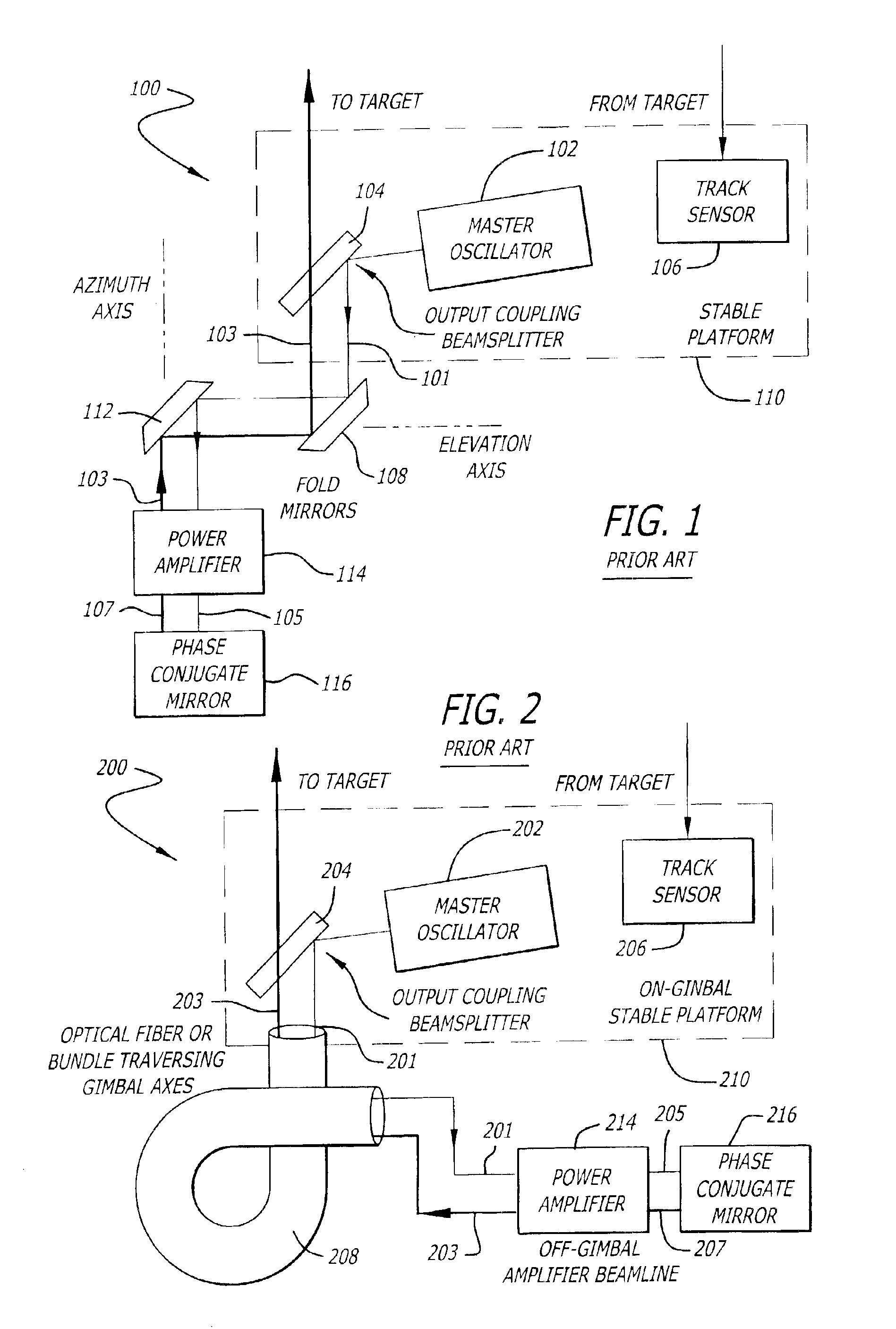
[0024]FIG. 1 is a block diagram showing a self-aligning phase conjugate laser concept disclosed by Byren and Rockwell in the early 1980s (U.S. Pat. Nos. 4,812,639 and 4,853,528) the teachings of which are incorporated herein by reference. ...


PUM


Abstract

A system for directing electromagnetic energy. The inventive system includes a first subsystem mounted on a first platform for transmitting a beam of the electromagnetic energy through a medium and a second subsystem mounted on a second platform for redirecting the beam. In accordance with the invention, the second platform is mobile relative to the first platform. In the illustrative embodiment, the beam is a high-energy laser beam. The first subsystem includes a phase conjugate mirror in optical alignment with a laser amplifier. The first subsystem further includes a beam director in optical alignment with the amplifier and a platform track sensor coupled thereto. In the illustrative embodiment, the second subsystem includes a co-aligned master oscillator, outcoupler, and target track sensor which are fixedly mounted to a stabilized platform, a beam director, and a platform track sensor. In the best mode, the stable platform is mounted for independent articulation relative to the beam director. A first alternative embodiment of the second subsystem includes first and second beam directors. The first beam director is adapted to receive the transmitted beam and the second beam director is adapted to redirect the received beam. In accordance with a second alternative embodiment, an optical fiber is provided for coupling the beam between the first platform and the second platform.

Description

BACKGROUND OF THE INVENTION[0001]1. Field of the Invention[0002]The present invention relates to systems and methods for directing electromagnetic energy. More specifically, the present invention relates to high-energy lasers and optical arrangements therefor.[0003]2. Description of the Related Art[0004]High-energy lasers are currently being used for, numerous military applications including point and area defense along with numerous offensive roles. Unfortunately, high-energy laser systems are typically expensive, heavy and quite large. These systems typically consume a large amount of prime power and present a high thermal load to a host platform.[0005]When used for surface ship self protection, a high-energy laser would suffer from atmospheric absorption, scattering and turbulence. For this application, incoming threats are attacked head-on, creating a targeting challenge and attacking the threat where it is least vulnerable. In addition, high-energy lasers located at the deck le...

Claims


Application Information

Patent Timeline
Patent Type & Authority Patents(United States)
IPC IPC(8): H01S3/00F41H11/02F41H13/00
CPCF41H11/02F41H13/0043F41H13/005
Inventor BYREN, ROBERT W.FILGAS, DAVID
Owner RAYTHEON CO
Why Eureka
Try Eureka