Chair for supporting wire mesh

a wire mesh and chair technology, applied in the direction of structures, buildings, roads, etc., can solve the problems of wire mesh bending, uneven surface of the grid, and the chair being rotated or otherwise forced off the grid, and the efforts of the wire mesh formed by the wire mesh to be twisted and uneven, etc., to achieve the effect of only partially successful at bes

Inactive Publication Date: 2005-11-08
JOHN L LOWERY & ASSOC
View PDF5 Cites 22 Cited by
  • Summary
  • Abstract
  • Description
  • Claims
  • Application Information

AI Technical Summary

Benefits of technology

[0009]Therefore, one object of this invention is to provide an improved compressible chair with the required resiliency that is less prone to cracking upon repeated compression-recovery action resulting during the use of the chairs.
[0010]Another object of this invention is to provide an improved compressible chair that can be constructed with less plastic.
[0011]Still another object of this invention is to provide a chair that better grips the wire mesh when a load is placed on the wire mesh.
[0016]In another preferred structure to provide additional stability the base member shall be in the form of a disk, preferably circular in shape, having an outside diameter at least 20% greater than the distance between the ends of the two legs forming one of the arches. In a more preferred embodiment the base member is provided with a central opening having a diameter less than the distance between the ends of the two legs forming one of the arches. In a still more preferred embodiment the base member has a support ridge around the perimeter of the central opening and is affixed to each of the legs attached to the base member. In another preferred embodiment the base member is also provided with at least one stabilizing ridge that extends inward from the perimeter of the disk to the raised ridge. More preferably, each stabilizing ridge will be affixed to one of the legs and there will be one stabilizing ridge for each leg of the support member arches.
[0017]In another preferred embodiment the setting comprises four flexible prongs shaped to form two pairs of aligned, opposing slots sized to permit the wires forming the mesh to be positioned in the opposing slots. Each pair of the slots is perpendicularly positioned with respect to the other pair of slots. Each slot has a wire receiving section, a wire retention section and a wire holding section. The wire receiving section is formed by the upper section edges of adjoining prongs and is preferably generally tapered from its upper edge to its lower edge. The wire retention section is formed by the middle section edges of adjoining prongs and has a width less than the diameter of the wire that is to be positioned in the wire holding section, but of sufficient width to permit the wire to be pushed through the wire retention section and into the wire holding section. The wire holding section is formed by the lower section edges of adjoining prongs and has a width slightly larger than the diameter of the wire. The setting is further provided with a brace member for each prong that is affixed to a corresponding prong and arch leg to cause the prong to bend inward grabbing the wire, rather than outward, when a load is placed on the setting. This action results in the gripping force on the wire being increased by the prongs as the load on the wire increases. Because of the cantilevering relationship between the chair and the wire when a load is placed on the wire, the likelihood that the chair will remain attached to the wire and not rotate or fall off the wire is increased. This feature permits the wire to be held in a vertical, sloping or horizontal position.

Problems solved by technology

However, in actual practice the grids do not remain in their initially arranged pre-selected positions.
This can result in the chairs being rotated or otherwise forced off the grid.
While these rigid chairs improved the maintenance of connection with the grid, the rigidity of chairs in many cases caused wire forming the wire mesh to bend and create uneven areas in the surface of the grid.
Such efforts are generally only partially successful at best.
One problem with the compressible, resilient chair has been the separation of the support legs from the setting resulting from repeated compression-recovery forces.
As the chairs become larger they become more expensive in large part due to the increased plastic material needed to construct the chair.

Method used


Image

  • Chair for supporting wire mesh
  • Chair for supporting wire mesh
  • Chair for supporting wire mesh

Examples


Embodiment Construction

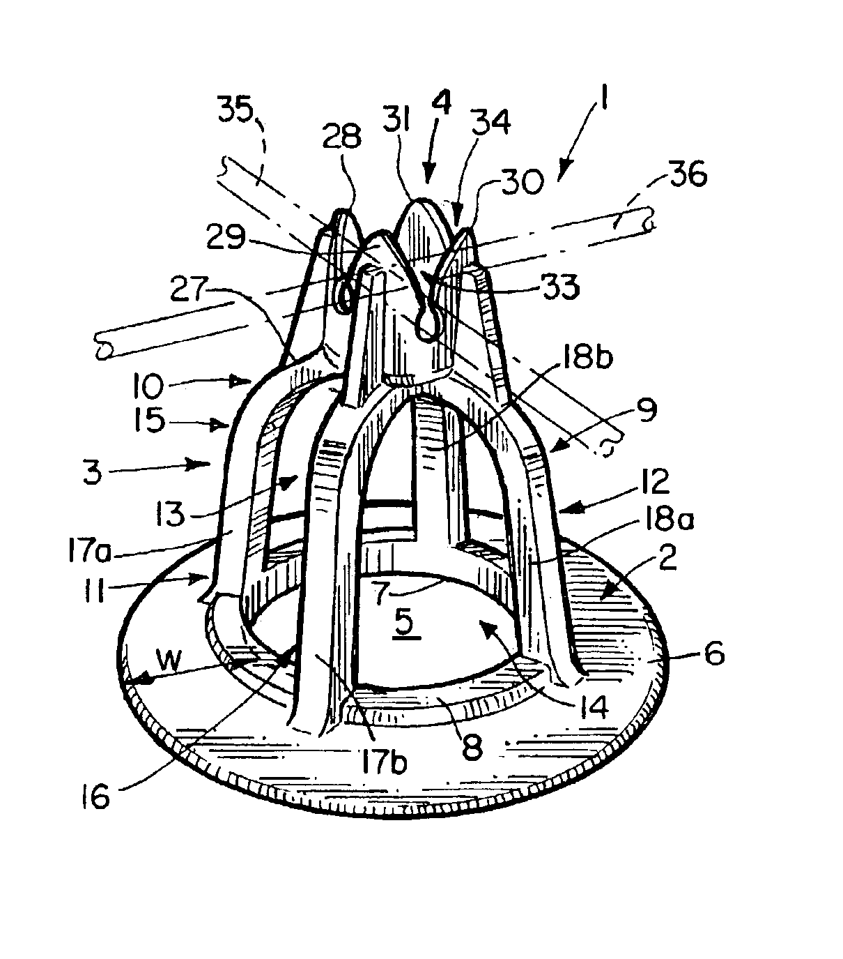
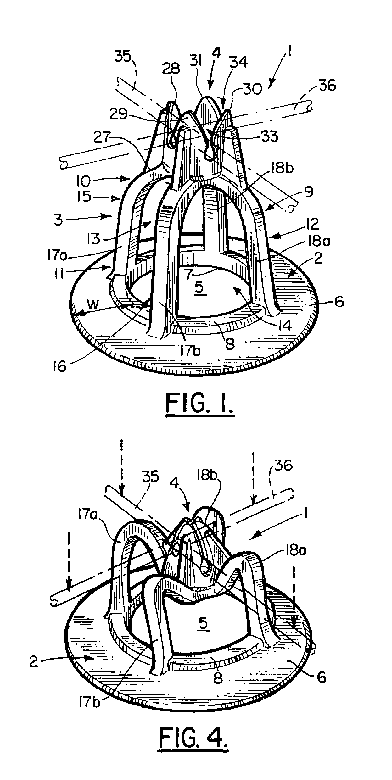
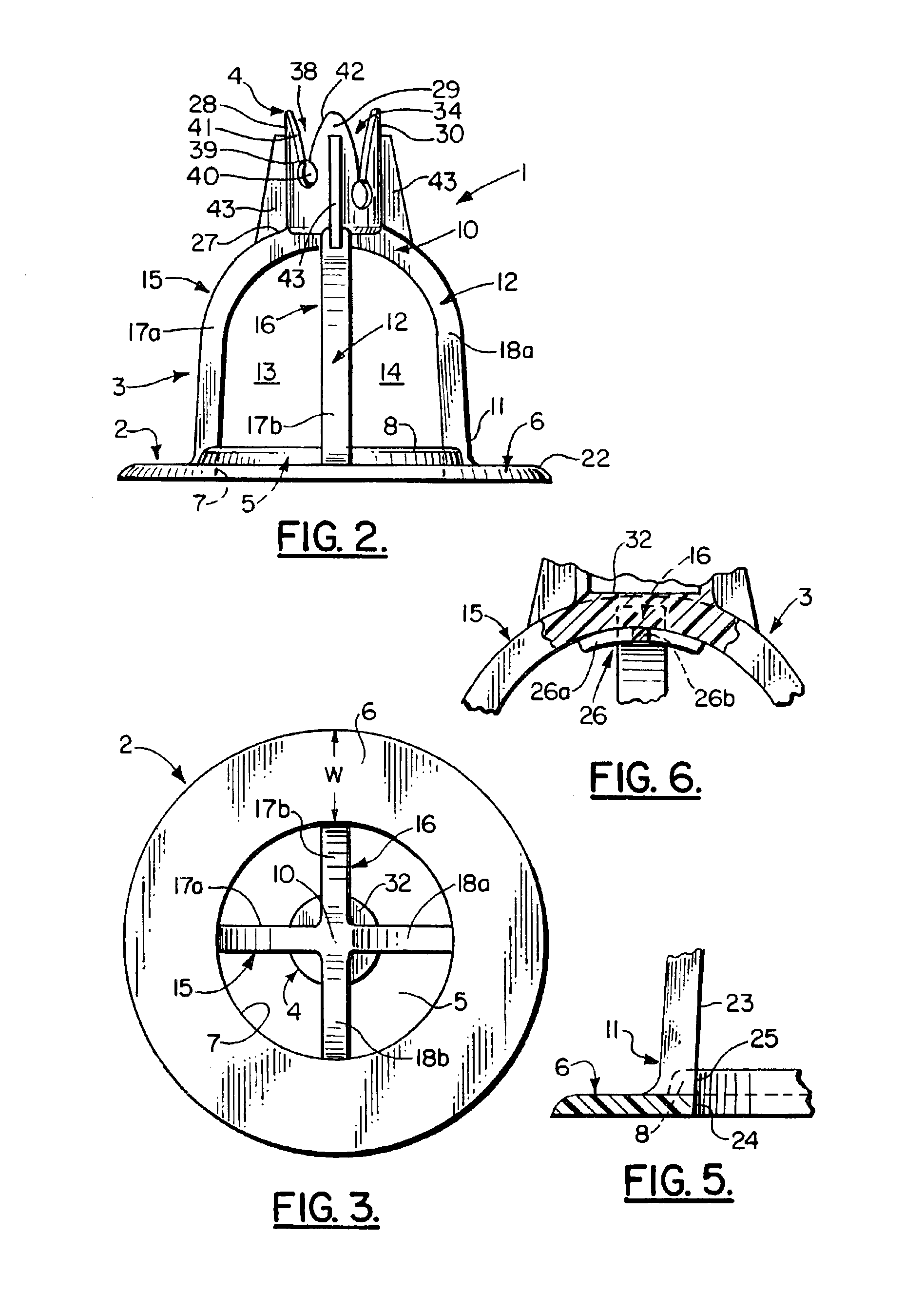
[0027]Without any intent to limit the scope of this invention, reference is made to the figures in describing the preferred embodiments of the invention. As seen in FIG. 1, the compressible chair 1 contains three basic elements. They are the base member 2, the support structure 3 and the setting 4. In the preferred embodiment shown base member 2 is disk-shaped having a central opening 5 forming a solid circular member 6 having a width “w” of at least 20% of the diameter of opening 5. Positioned about the perimeter 7 of opening 5 is a raised ridge 8.

[0028]The support structure 3 is generally bell shaped, preferably with its continuous side wall 9 tapered outward from its upper section 10 to its lower section 11. In the middle section 12 of the side wall 9 are two pairs of opposing arched-shaped openings 13, 14 forming two perpendicularly intersecting arches 15, 16 that form the upper section 10. Each arch 15 and 16 has a pair of opposing compressible, resilient legs 17a, 18a and 17b,...


PUM

PropertyMeasurementUnit
resiliencyaaaaaaaaaa
flexibleaaaaaaaaaa
diameteraaaaaaaaaa

Abstract

An improved chair for supporting intersecting wires forming a wire mesh at a pre-selected elevated position above a bearing surface during formation of a concrete slab is constructed having a base member shaped to rest on the bearing surface, a compressible support structure having a lower section affixed to the base member, a middle section and an upper section affixed to a setting shaped to support the wire mess at the elevated position. The chair is constructed having an improved compressible, generally bell-shape support structure having two pairs of opposing arched-shaped openings in the middle section forming two intersecting arches, each arch having a pair of opposing flexible legs that bow outward when a pre-determined load is applied to the upper section. The support structure further having a strengthening plate affixed on an interior surface of the upper section of the support structure formed by the intersecting arches. The chair constructed from a blend of high density and low density crystalline polymer.

Description

BACKGROUND OF THE INVENTION[0001]1. Field of the Invention[0002]This invention relates in general to chairs for supporting reinforcement bars or wire mesh at a pre-selected elevated position above a bearing surface during the formation of a concrete slab, and more particularly to non-rigid chairs that are compressible when receiving a predetermined minimum load and resilient to return to their original shape when the load is reduced below the predetermined minimum load.[0003]2. Prior Art[0004]Concrete and many plastic compositions have a relative weak tensile strength. When used to form a slab these compositions will be placed in tensile stress from imposed loads, thermally induced changes or solidification upon setting. To increase the tensile strength of the slab, reinforcing wire fabrics, rigid metal bars, grids formed by relatively thin wire compression welded to one another at their points of intersection, and frameworks are employed as skeletal reinforcing members.[0005]It is ...

Claims


Application Information

Patent Timeline
Patent Type & Authority Patents(United States)
IPC IPC(8): E04C5/16E04C
CPCE04C5/168E04C5/20
Inventor LOWERY, JOHN LESLIELOWERY, VIRGINIA SABATIER
Owner JOHN L LOWERY & ASSOC
Why Eureka
Try Eureka