Method for employing an extendible stent apparatus

Inactive Publication Date: 2005-11-08
BOSTON SCI SCIMED INC
View PDF319 Cites 158 Cited by
  • Summary
  • Abstract
  • Description
  • Claims
  • Application Information

AI Technical Summary

Benefits of technology

[0020]Yet another object of the invention is to provide a singl

Problems solved by technology

One of the drawbacks of conventional stents is that they are produced in a straight tubular configuration.
The use of such stents to treat disease at or near a branch or bifurcation of a vessel runs the risk of compromising the degree of patency of the primary vessel and/or its branches or bifurcation and also limits the ability to insert a second stent into the side branch if the angioplasty result is suboptimal.
The risk of branch compromise is increased in two anatomical situations.
First the side branch can be compromised when there is a stenosis in the origin of the side branch.
Second, when there is an eccentric lesion at the bifurcation site, asymmetric expansion can cause either plaque shifting or dissection at the side branch origin.
There are reports of attempting to solve this problem by inserting a balloon into the side branch through the stent struts; however, this technique carries the risk of balloon entrapment and other major complications (Nakamura, S. et al., Catheterization and Cardiovascular Diagnosis 34: 353-361 (1995)).
Moreover, adequate dilatation of the side branch is limited by elastic recoil of the origin of the side branch.
In addition, the stent may pose a limitation to blood flow and may limit access to the side branch.
In this regard, the tubular slotted hinged design of the Palmaz-Schatz intracoronary stent, in particular, is felt to be unfavorable for lesions with a large side branch and it is believed to pose a higher risk of side branch vessel entrapment where the stent prevents or limits access to the side branch.
The removal of the guidewire poses the risk of occlusion of the side branch during the deployment of the stent in the main branch.
However, none of these patents relate to the treatment of bifurcation lesions, or disclose a bifurcating stent apparatus and method for deploying the same.
It does not reinforce the vessel wall, nor does it prevent restenosis after angiop

Method used


Image

  • Method for employing an extendible stent apparatus
  • Method for employing an extendible stent apparatus
  • Method for employing an extendible stent apparatus

Examples


Embodiment Construction

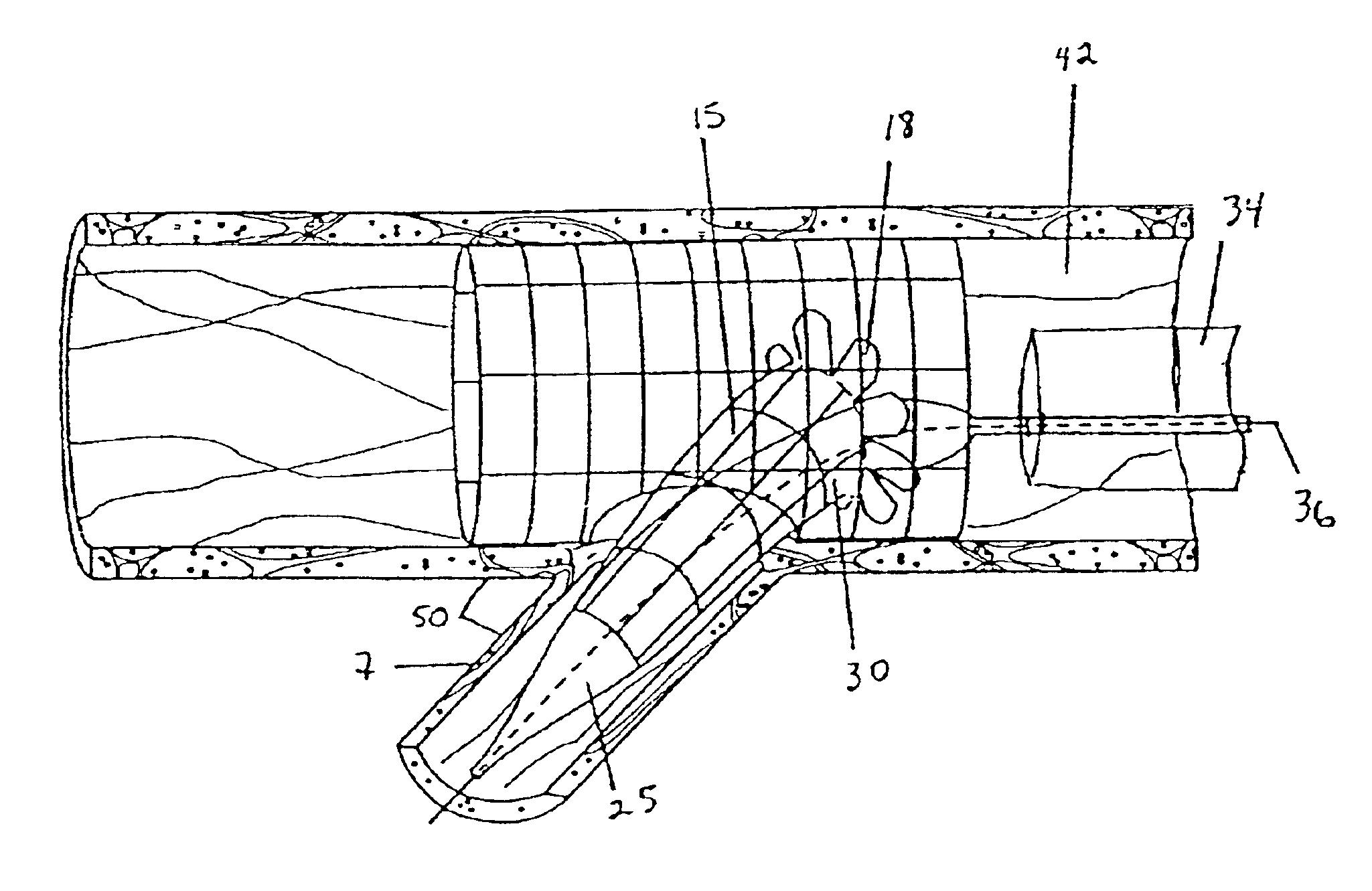
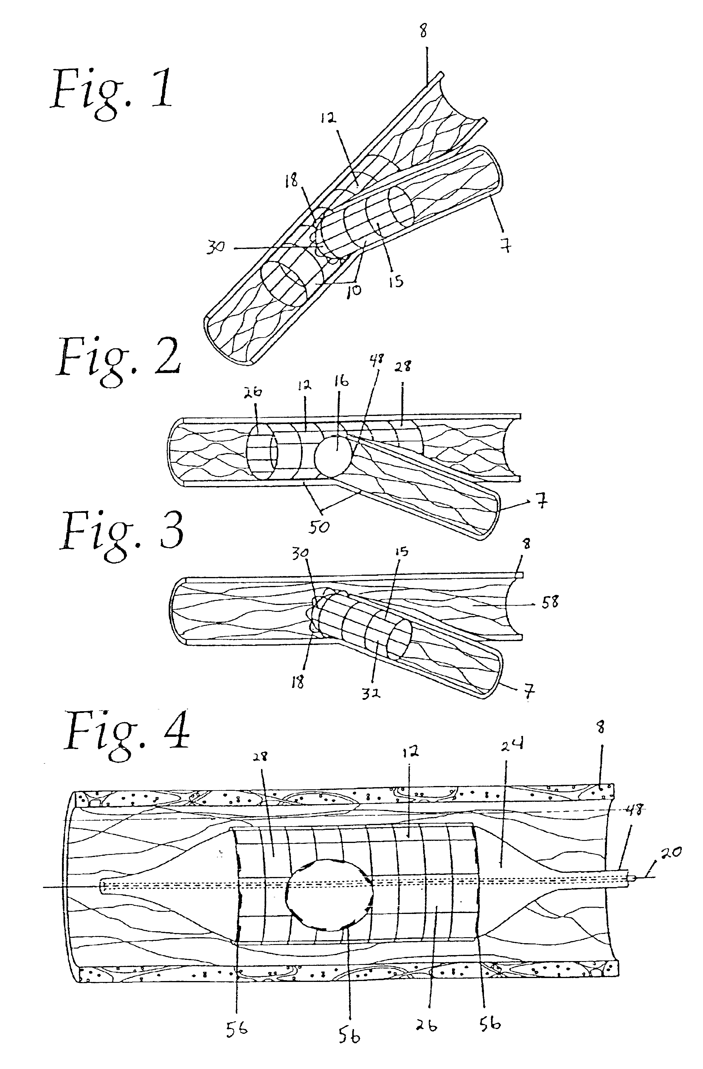
[0037]The bifurcating double-stent apparatus 10 of the present invention comprises a generally cylindrical main stent 12 and a generally cylindrical flared stent 15, which are shown as fully dilated in a subject main vessel 8 and a subject branch vessel 7, as illustrated in FIG. 1.

[0038]The main stent 12 contains at least one generally circular opening 16 located between the proximal end 26 and the distal end 28 of the main stent 12 (FIG. 2), which opening is positioned over the opening 48 of a branch vessel in a vessel bifurcation 50, as shown in FIG. 2. The ends of the stent 12 and the opening are imaged during imaging procedures by placing markers 56 around the edges of the opening 16 in the main stent 12 and at the proximal end 26 and distal end 28 of the main stent, as illustrated in FIG. 4.

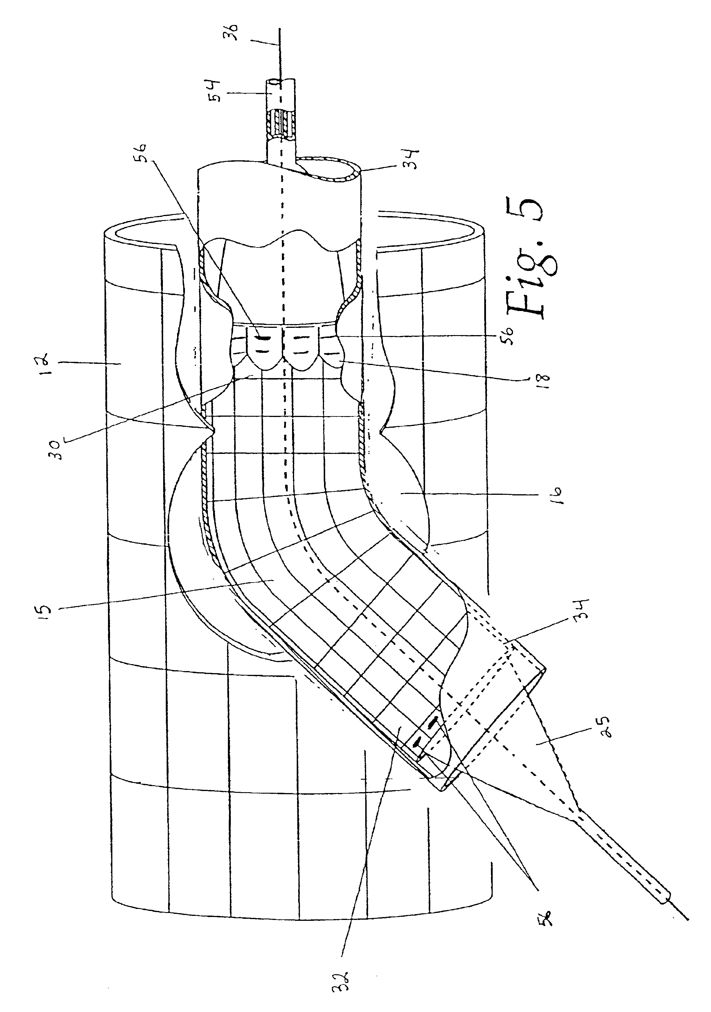
[0039]The flared stent apparatus 15 of the present invention comprises a generally cylindrical flared stent comprising a proximal end 30 and a distal end 32, as shown in FIG. 3. The proximal...


PUM


Abstract

An imageable extendable stent apparatus for insertion into a bifurcating vessel or a vessel opening. The stent apparatus comprises a main stent and a flared stent, which may used individually or in combination with each other. The flared stent may be interlocked with the main stent to provide stent coverage over the entire region of a bifurcation. The main stent of the apparatus may be deployed at the bifurcation point of a vessel, allowing unimpeded future access to the side branch of the bifurcated vessel. The flared stent may be employed at vessel openings. Also disclosed and claimed are methods for implanting the extendable stent apparatus into the bifurcation point or the ostium of a subject vessel.

Description

[0001]This application is a continuation of U.S. Ser. No. 08 / 935,363 filed Sep. 23, 1997 (now abandoned), which is a divisional application of U.S. Ser. No. 08 / 744,002 filed Nov. 4, 1996 (now abandoned).BACKGROUND[0002]A type of endoprosthesis device, commonly referred to as a stent, is placed or implanted within a vein, artery or other tubular body organ for treating occlusions, stenoses, or aneurysms of the vessel. These stent devices are implanted within tubular vessels to reinforce collapsing, partially occluded, weakened, or abnormally dilated segments of the vessel wall. Stents have been used to treat dissections in blood vessel walls caused by balloon angioplasty of the coronary arteries as well as peripheral arteries and to improve angioplasty results by preventing elastic recoil and remodeling of the vessel wall.[0003]Stents also have been successfully implanted in the urinary tract, the bile duct, the esophagus and the tracheo-bronchial tree to reinforce those body organs....

Claims


Application Information

Patent Timeline
IPC IPC(8): A61F2/06A61F2/00A61F2/82
CPCA61F2/856A61F2/91A61F2/915A61F2/954A61F2/958A61F2/852A61F2002/821A61F2002/91525A61F2002/91533A61F2250/006A61F2250/0098A61F2/064A61F2/07A61F2/82A61F2002/067A61F2002/91508A61F2002/91516A61F2002/9155A61F2002/91558A61F2002/91575A61F2002/91583
Inventor VARDI, GIL M.DAVIDSON, CHARLES J.
Owner BOSTON SCI SCIMED INC
Why Eureka
Try Eureka