Solar cell module and its installing module

a solar cell module and installation module technology, applied in the field of solar cell modules, can solve the problems of low generation efficiency, variation in the amount of photo-generated current, and the failure of oeco solar cell modules to equalize the output current of individual solar cells, and achieve the effect of increasing the daily or annual power generation fully expressing the performance of the solar cell modul

Inactive Publication Date: 2005-11-08
SHIN ETSU CHEM IND CO LTD
View PDF21 Cites 11 Cited by
  • Summary
  • Abstract
  • Description
  • Claims
  • Application Information

AI Technical Summary

Benefits of technology

[0013]Examinations by the inventors have revealed that the OECO solar cell, having the electrode-forming inner side face only on a single side face of each groove, showed completely different patterns of intensity of sunlight coming into the electrode, severity of the shadowing, and daily or annual variation thereof depending on the attitude of the module or on the latitude of the installation site. Whereas the invention succeeded in fully expressing performances of the solar cell module, and, as a consequence, in increasing the daily or annual power generation of the solar cell module, by defining an angle of inclination β of the light-receiving surfaces of the individual solar cells away from the horizontal plane as the attitude of the module, and by adjusting the direction of arrangement of the electrode-forming inner side faces depending on p and the latitude δ of the installation site.

Problems solved by technology

On the contrary, the electrode prevents sunlight from entering the semiconductor material composing the solar cells, and consequently lowers the generation efficiency.
The electrode, typically formed by screen printing using an Ag paste, accounts for 8 to 12% of the total area of the light-receiving surface of the solar cells, and shadowing loss ascribable to this is understood as an obstacle to efforts for improving the generation efficiency.
Because the OECO solar cell has the electrodes only on one side face of each groove, the shadowed area will vary depending on the angle of incidence of sunlight, and thus the cell inevitably causes variation in the amount of photo-generated current.
The OECO solar cell module is, however, not always successful in equalizing the output current from the individual solar cells even if it is configured using solar cells having a uniform basic performance, and even the cells are uniformly irradiated by sunlight.
It is because severity of the shadowing loss may differ from cell to cell and the output current may be non-uniform under an oblique incidence of sunlight if no special attention is paid on the direction of attachment of the individual cells in the module.
Considering now that solar cell modules are generally installed on the roof of houses or buildings, and that the OECO solar cell has electrodes only on a single side face of each groove and shows the shadowing loss variable depending on the angle of incidence of sunlight as described in the above, another disadvantage arises that total of daily or annual power output may differ depending on the direction to which the electrode-forming surfaces are directed, and this may prevent performance of the solar cell module from being fully exhibited.

Method used


Image

  • Solar cell module and its installing module
  • Solar cell module and its installing module
  • Solar cell module and its installing module

Examples


example 1

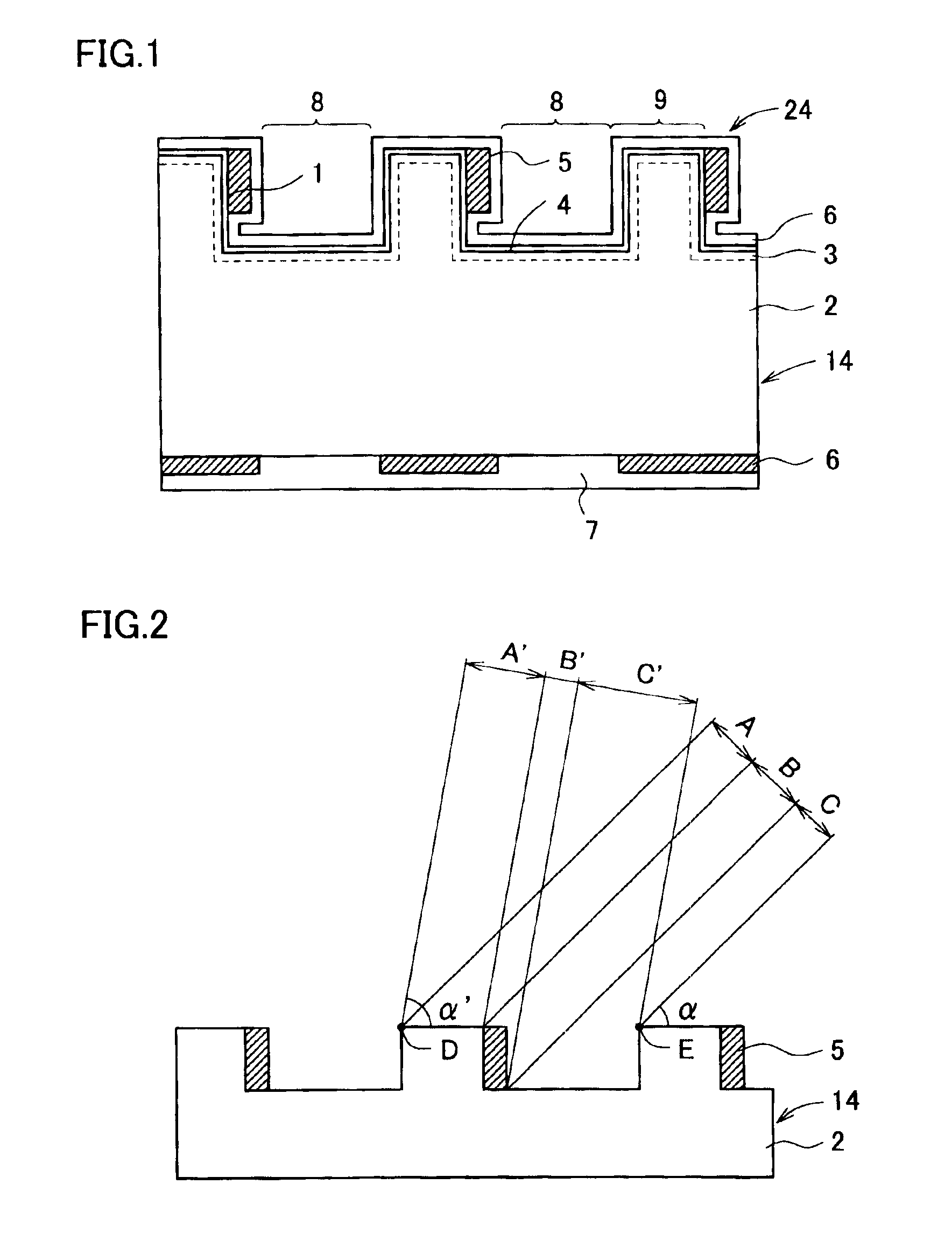
[0065]The solar cell shown in FIG. 1 was fabricated by the method described below. First, on the light-receiving surface side of the p-type, single crystal silicon wafer 2 containing gallium, a Group III element, as an impurity (10 cm square, 300 μm thick, specific resistance 0.5 Ω·cm), a plurality of parallel grooves 8 having a square (rectangular) section were formed using a dicer. The groove morphology was defined, as shown in FIG. 19, by a distance (w1) between the grooves of 50 μm, a width (w2) of the groove of 450 μm, and a depth (h) of the groove of 50 μm. Damaged layer produced in the wafer was then removed by etching using an aqueous potassium hydroxide solution, and the silicon nitride film 6 was formed on the back surface using a plasma-assisted CVD apparatus.

[0066]The emitter layer 3 comprising an n+-type region was then formed on the light-receiving surface side of the silicon wafer 2 by thermally diffusing phosphorus, which is a Group V element, so as to adjust the she...

example 2

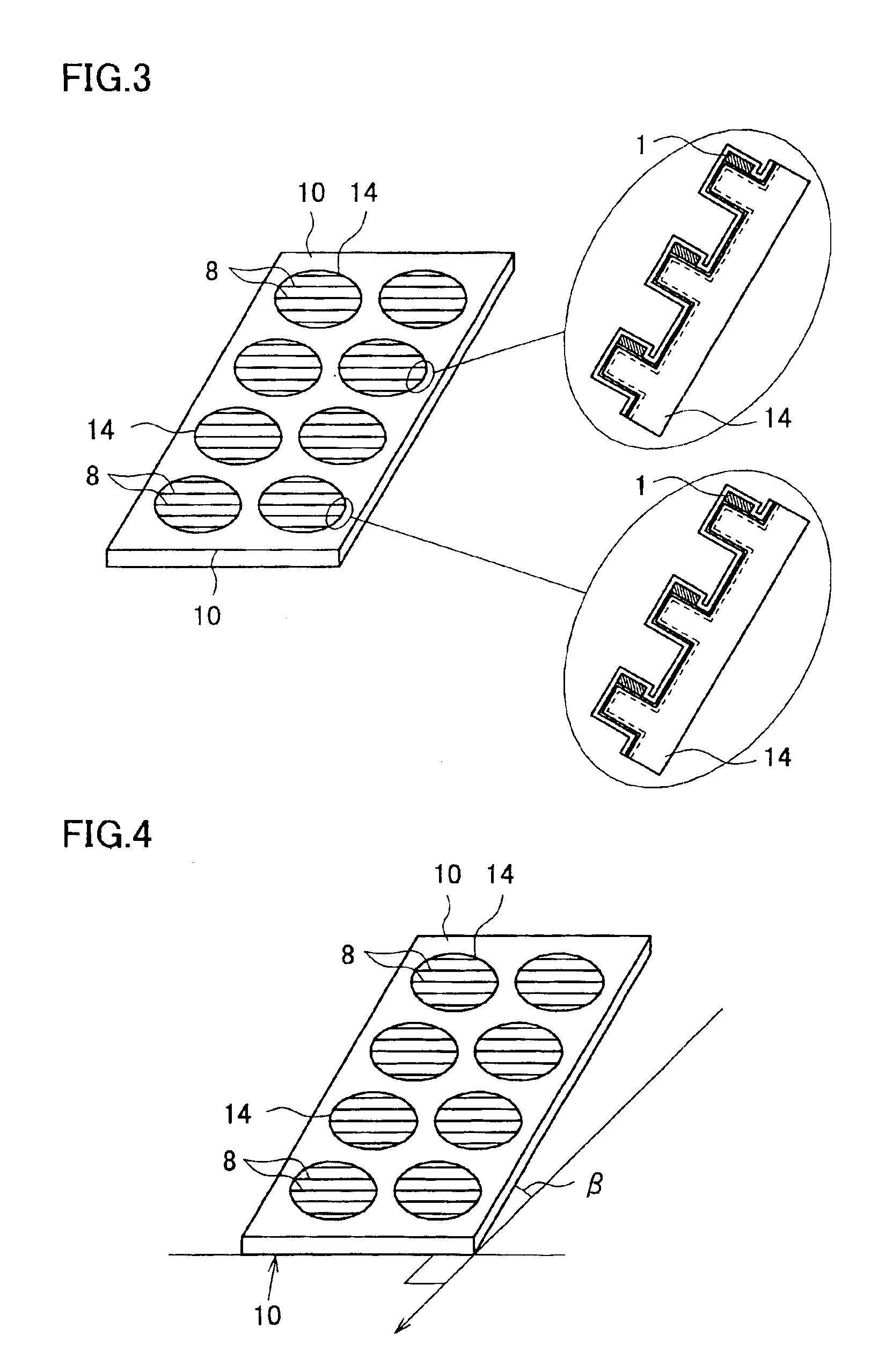
[0071]As judged from the discriminants (1) and (2) of the invention, the installation at 30° North Latitude and at an installation angle of 35° can yield optimum results when the electrode-forming inner side faces are directed downward. For a demonstration purpose, the inventors installed the solar cell module fabricated in Example 1, in which all electrode-forming inner side faces 1 are unidirectionally aligned, on a roof having a slope inclined 35° away from due south in Yaku Island, Kagoshima Prefecture, Japan situated at 30°20″ North Latitude, and the annual power output was measured. Samples used herein were one solar cell module having electrode-forming inner side faces directed upward and one solar cell module having those directed downward. Measurement results of the annual power output were listed in Table 2.

[0072]

TABLE 2Module havingModule having electrode-electrode-forming innerforming inner side faceside face directeddirected downwardupwardAnnual power118.7117.9output (k...


PUM


Abstract

A solar cell module 60 has a plurality of solar cells 14 having a plurality of parallel grooves 8 on the individual light-receiving surfaces thereof, each of the grooves having an electrode 5 for extracting output on the inner side face (electrode-forming inner side face) on one side in the width-wise direction thereof; and a support 10, 50 for supporting the solar cells 14 in an integrated manner so as to direct the light-receiving surfaces upward. The annual power output can be increased by adjusting the direction of arrangement of the electrode-forming inner side faces of the grooves 8 while taking the angle of inclination β of the light-receiving surface of the individual as-installed solar cells 14 relative to the horizontal plane and the latitude δ of the installation site of the solar cell module into consideration.

Description

TECHNICAL FIELD[0001]This invention relates to a solar cell module and a method of installing the solar cell module.BACKGROUND ART[0002]Solar cells generally have a finger-type electrode on the surface thereof for the purpose of extracting generated power to the external. It is preferable for the electrode to have a larger width or larger thickness in view of improving the generation efficiency, since the larger the sectional area of the electrode becomes, the more the electrode reduces its resistivity. On the contrary, the electrode prevents sunlight from entering the semiconductor material composing the solar cells, and consequently lowers the generation efficiency. The electrode, typically formed by screen printing using an Ag paste, accounts for 8 to 12% of the total area of the light-receiving surface of the solar cells, and shadowing loss ascribable to this is understood as an obstacle to efforts for improving the generation efficiency.[0003]One known method ever developed in ...

Claims


Application Information

Patent Timeline
Patent Type & Authority Patents(United States)
IPC IPC(8): H01L31/042H01L31/04E04D13/18
CPCF24J2/541H01L31/022425H01L31/035281H01L31/03529H02S20/24H01L31/02H02S20/30H02S20/23F24J2002/5486Y02E10/47Y02E10/50Y02B10/12F24S2030/16F24S30/425Y02B10/10H02S20/20H01L31/042
Inventor OJIMA, SATOYUKIOHTSUKA, HIROYUKITAKAHASHI, MASATOSHIWATABE, TAKENORIABE, TAKAO
Owner SHIN ETSU CHEM IND CO LTD
Why Eureka
Try Eureka