Position information input apparatus and method

a position information and input apparatus technology, applied in static indicating devices, instruments, optics, etc., can solve the problems of increasing the difficulty of achieving the effect of the apparatus using a psd having a high tolerance to ambient light, and the increase of the cost and size of the apparatus

Inactive Publication Date: 2005-11-08
CANON KK
View PDF15 Cites 40 Cited by
  • Summary
  • Abstract
  • Description
  • Claims
  • Application Information

AI Technical Summary

Problems solved by technology

The resolving power in a coordinate input apparatus must also be increased, but this is difficult to achieve in an apparatus using a PSD having a high tolerance to ambient light.
Accordingly, the apparatus increases in cost and size.
Such a method makes an apparatus increase in cost and size, and if a video camera having many pixels is used in the apparatus, it increases the apparatus' cost and size more than using a plura

Method used


Image

  • Position information input apparatus and method
  • Position information input apparatus and method
  • Position information input apparatus and method

Examples


third embodiment

The Third Embodiment

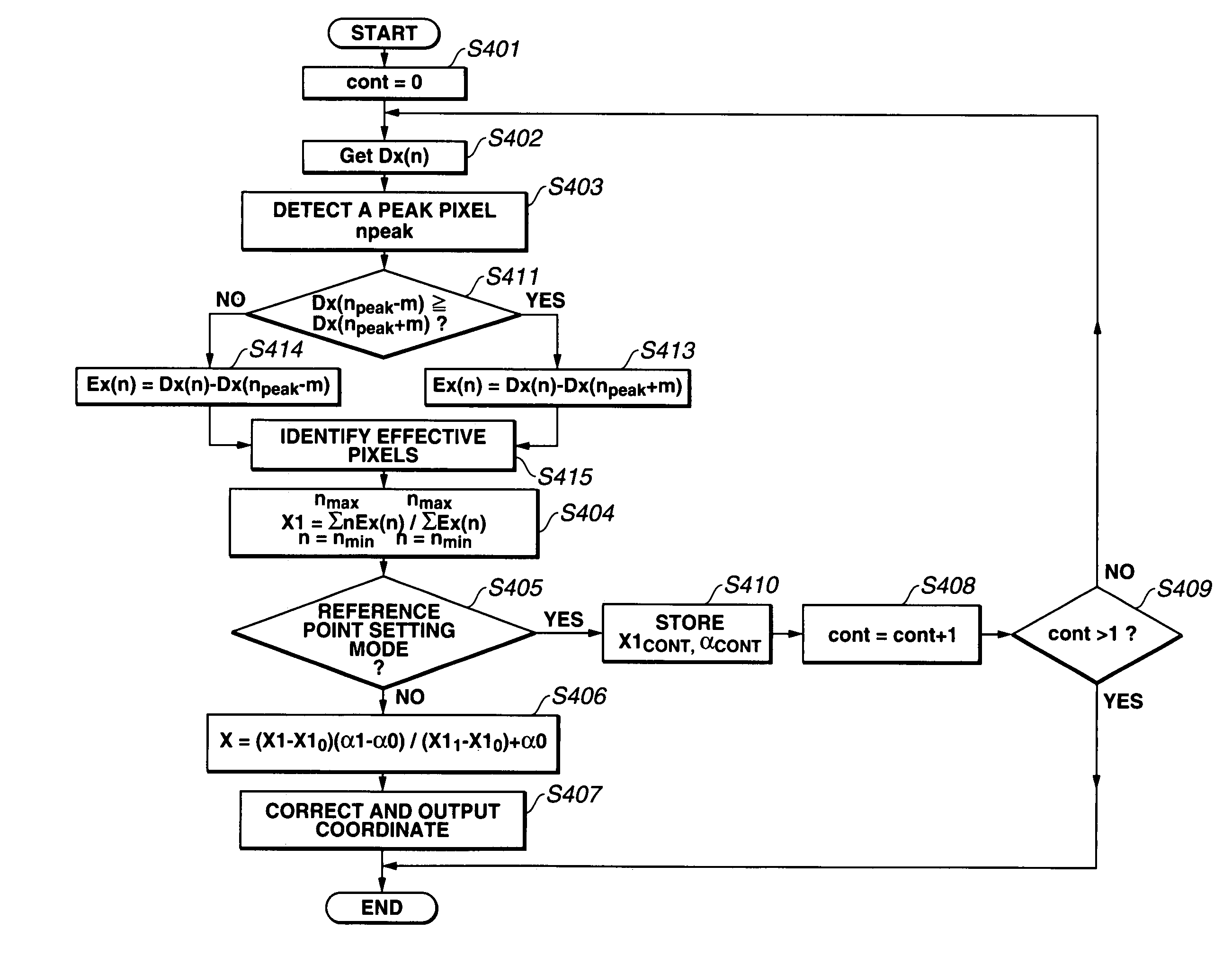
[0136]FIG. 17 is a flowchart showing a coordinate calculation processing according to the third embodiment. After the processing has started in FIG. 17, a variable cont is set to 0 for initializing in step S401, and difference data Dx(n) corresponding to a difference signal at each coordinate input device is read out and stored in the buffer in step S402. Next, a pixel npeak where output signal becomes maximum is detected in step S403, m-th pixels in each direction forward and backward from the pixel npeak are selected, and the signal levels of both selected pixels Dx(npeak−m) and Dx(npeak+m) are compared in step S411. The smaller of the signal levels is set as a threshold value based on the comparison, and the output signals of each of the pixels are compared with the threshold value in step S413 or step S414. The smaller one is set as the threshold value in this embodiment, and FIG. 14(A) shows a case where m=3. In the figure, it is clear that the threshold val...

fourth embodiment

The Fourth Embodiment

[0142]In this embodiment, a determination is made as to whether or not the set threshold value is effective for identifying the receiving light, which is the light emitted from the light source arranged in the designating device. The determination provides higher accuracy and reliability in coordinate detection. If the products using the sensor are manufactured in quantity, the differences between products and their parts should be considered. Especially, the output voltage when no light reaches the sensor, namely output voltage in a dark condition, is a problem. The output voltage in a dark condition usually varies by plus and minus dozens of percent from the nominal value, due to manufacturing tolerances. The distribution is from about 0.7 V to about 1.3 V depending on the difference between each product if the electric source voltage is 5 V and it is assumed that the nominal output voltage in a dark condition is 1 V. Therefore, the threshold level must be set...


PUM


Abstract

The invention aims to provide a coordinate input apparatus having high detection reliability and high efficiency and to control the influence of ambient light using a simple structure. The apparatus detects a light spot flashing on and off in a predetermined cycle and incident at a desired position on a coordinate input screen, and includes a detection device having photoelectric conversion elements corresponding to N pixels for detecting a light spot coordinate. The difference between signals from photoelectric elements in light emission state and in light non-emission state at each N pixel is found, and the smaller of the difference signals of the m-th pixel having the maximum difference signal is set as a threshold value. Effective pixels are identified based on the threshold value, and the coordinate is calculated by using the difference data of the selected effective pixels.

Description

BACKGROUND OF THE INVENTION[0001]1. Field of the Invention[0002]The present invention relates to a method and apparatus for inputting position information such as coordinate data, particularly for use with a large screen display system. In detail, the present invention relates to a position information input apparatus and method for generating position information such as a coordinate expressing a position designated on a display screen by an operator. The operator may use a designation device for designating the position. The input position information can be used for controlling an externally connected computer, or for writing characters and graphics.[0003]2. Description of Related Art[0004]Some of the prior coordinate input devices sense a light spot on the screen by using a CCD area sensor or linear sensor. The devices calculate and output coordinate values by performing an image processing using centroid coordinates, pattern matching, etc. Some of the prior coordinate input dev...

Claims


Application Information

Patent Timeline
IPC IPC(8): G06F3/033G01B11/00G06F3/041G06F3/042
CPCG06F3/0386G06F3/0425
Inventor KOBAYASHI, KATSUYUKIHASEGAWA, MASAHIDEKOBAYASHI, KIWAMUKANASHIKI, MASAAKITANAKA, ATSUSHIYOSHIMURA, YUICHIRO
Owner CANON KK
Why Eureka
Try Eureka