
System and method for calculating aerial image of a spatial light modulator

a spatial light modulator and aerial image technology, applied in the field of lithography, can solve the problems of increasing the cost and time of reticle manufacture, the reticle can only be used for a certain period of time before being worn out, and the routine cost of further costs

Active Publication Date: 2005-11-08
ASML HLDG NV
View PDF29 Cites 18 Cited by
  • Summary
  • Abstract
  • Description
  • Claims
  • Application Information

AI Technical Summary

Benefits of technology

The present invention is a system and method for calculating an aerial image using a spatial light modulator. The method includes steps of calculating a pixel interference matrix to represent interference between pixels, calculating effective graytones to represent modulation states of the pixels, and calculating the aerial image based on the pixel interference matrix and the effective graytones. The invention has advantages over related art methods, as it can account for position variables and can use sinc or polynomial functions to approximate the effective graytones.

Problems solved by technology

These reticles are becoming increasingly costly and time consuming to manufacture due to the feature sizes and the exacting tolerances required for small feature sizes.
Also, a reticle can only be used for a certain period of time before being worn out.
Further costs are routinely incurred if a reticle is not within a certain tolerance or when the reticle is damaged.
Thus, the manufacture of wafers using reticles is becoming increasingly, and possibly prohibitively expensive.
However, conventional “brute force” approaches to such calculations are extremely computationally intensive, which usually makes it impossible to continuously re-compute the aerial images in real time.

Method used


Image

  • System and method for calculating aerial image of a spatial light modulator
  • System and method for calculating aerial image of a spatial light modulator
  • System and method for calculating aerial image of a spatial light modulator

Examples


Embodiment Construction

[0027]While specific configurations and arrangements are discussed, it should be understood that this is done for illustrative purposes only. A person skilled in the pertinent art will recognize that other configurations and arrangements can be used without departing from the spirit and scope of the present invention. It will be apparent to a person skilled in the pertinent art that this invention can also be employed in a variety of other applications.

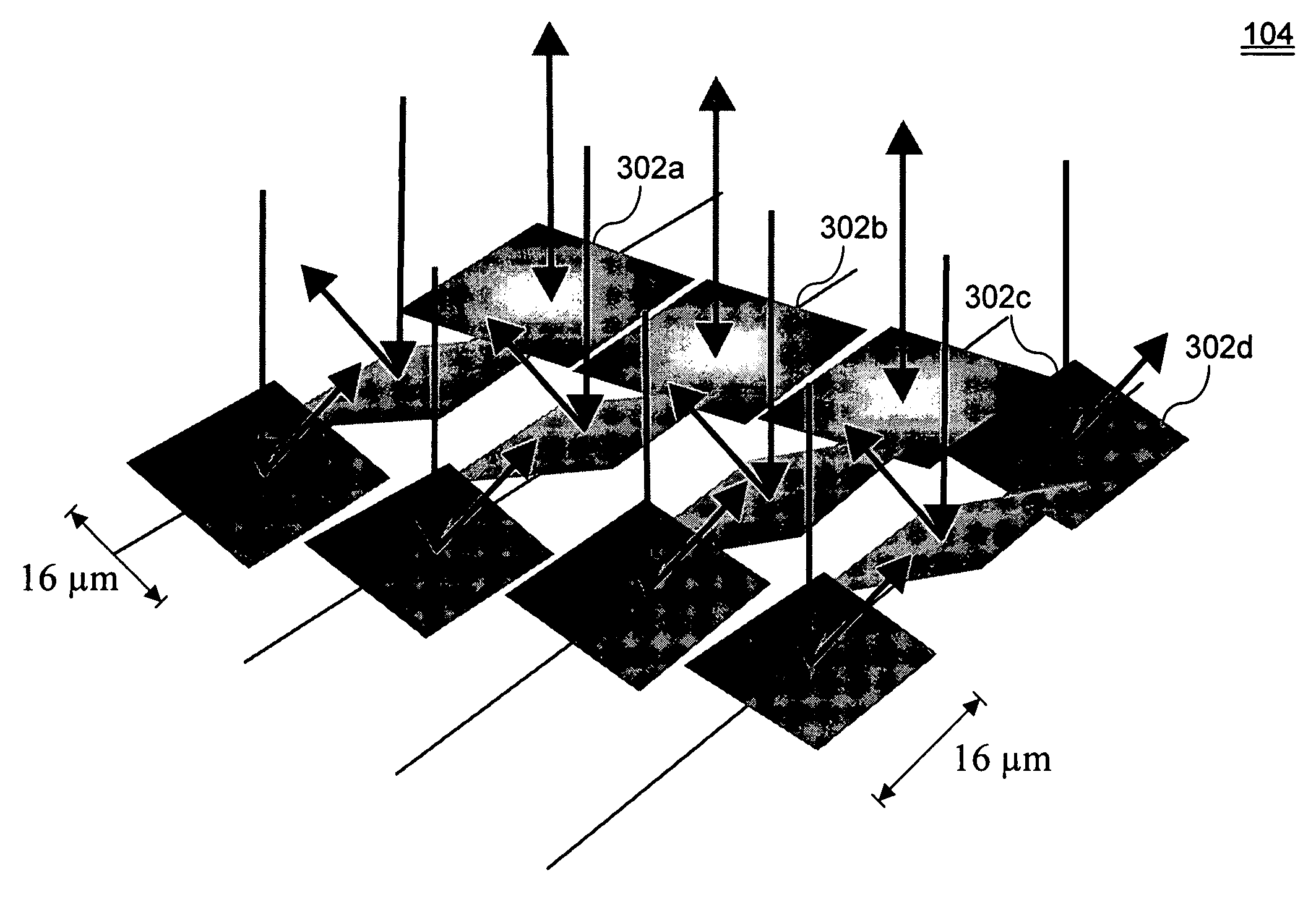
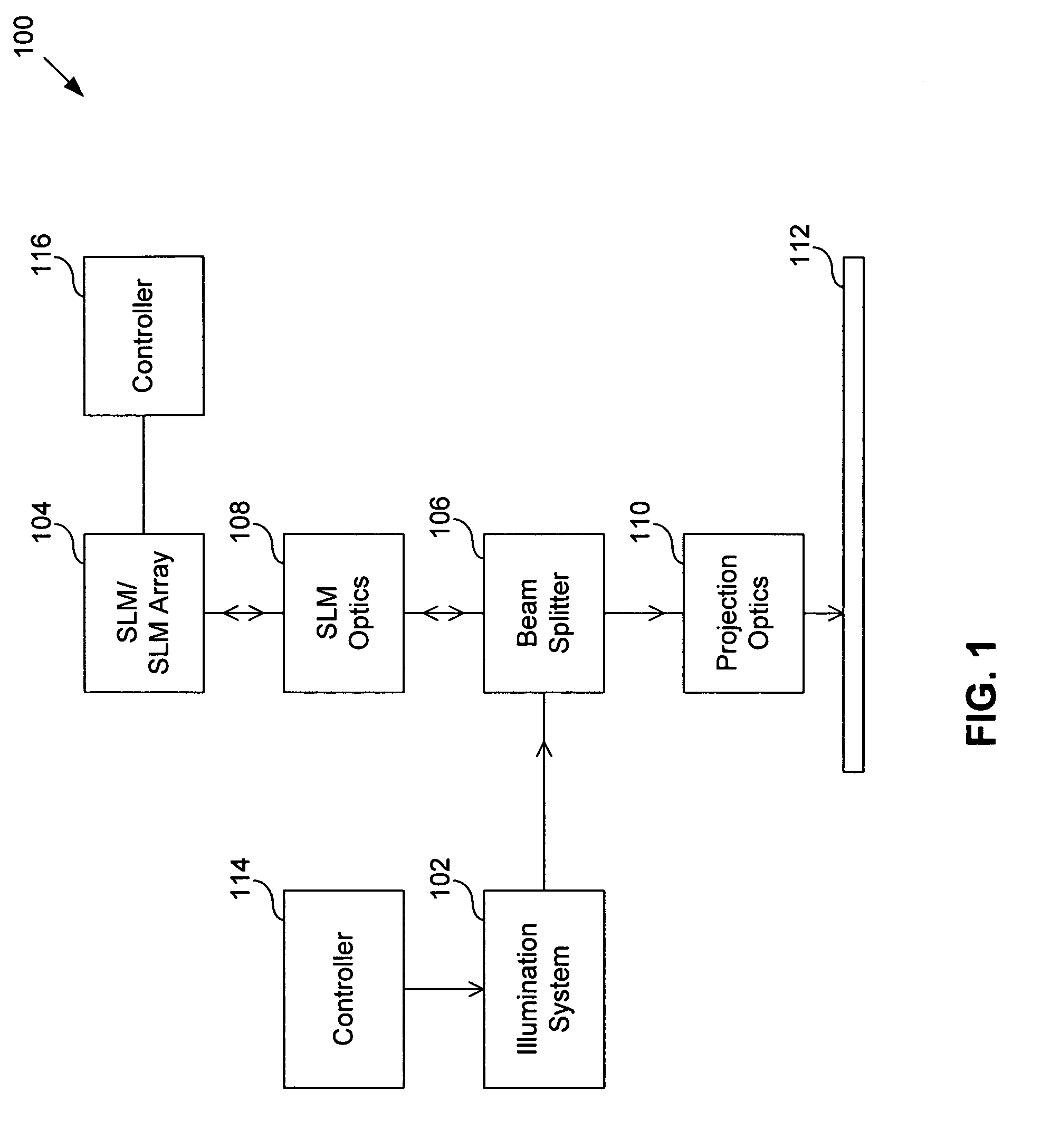
[0028]FIG. 1 shows a maskless lithography system 100 according to an embodiment of the present invention. System 100 includes an illumination system 102 that transmits light to a reflective spatial light modulator (SLM) 104 (e.g., a digital micromirror device (DMD), a reflective liquid crystal display (LCD), or the like) via a beam splitter 106 and SLM optics 108. SLM 104 is used to pattern the light in place of a reticle used in traditional lithography systems. Patterned light reflected from SLM 104 is passed back through beam splitt...


PUM

PropertyMeasurementUnit
transmittanceaaaaaaaaaa
electromagnetic radiationaaaaaaaaaa

Abstract

A method of calculating an aerial image of a spatial light modulator array includes calculating a pixel interference matrix that represents pair wise interference between pixels of the spatial light modulator array; calculating effective graytones corresponding to modulation states of the pixels; and calculating the aerial image based on the pixel interference matrix and the effective graytones. The graytones depend only on the modulation states of the pixels. The pixel interference matrix depends only on position variables. The position variables are position in an image plane and position in a plane of a source of electromagnetic radiation. The pixel interference matrix can be a matrix of functions. The pixel interference matrix can be a four dimensional matrix. The effective graytones are approximated using sinc functions, or using polynomial functions.

Description

BACKGROUND OF THE INVENTION[0001]1. Field of the Invention[0002]The present invention relates generally to lithography. More particularly, the present invention relates to real-time calculations of an aerial image of a spatial light modulator (SLM) array.[0003]2. Related Art[0004]Lithography is a process used to create features on the surface of substrates. Such substrates can include those used in the manufacture of flat panel displays (e.g., liquid crystal displays), circuit boards, various integrated circuits, and the like. A frequently used substrate for such applications is a semiconductor wafer or glass substrate. While this description is written in terms of a semiconductor wafer for illustrative purposes, one skilled in the art would recognize that this description also applies to other types of substrates known to those skilled in the art.[0005]During lithography, a wafer, which is disposed on a wafer stage, is exposed to an image projected onto the surface of the wafer by ...

Claims


Application Information

Patent Timeline
Patent Type & Authority Patents(United States)
IPC IPC(8): G02B26/00G02F1/00G03B27/42G03F9/00G03F1/00G09G5/02H04N11/06H04N11/20H01L21/027G03F7/20
CPCG03F7/70283G03F7/70291G03F7/70666G03F7/705G03F7/70508G03F7/70441G03F7/2051
Inventor LATYPOV, AZAT M.
Owner ASML HLDG NV
Learn More