Footwear with impact absorbing system

a technology of impact absorption and footwear, applied in the field of footwear, can solve the problems of increasing the impact force, increasing the impact on the wearer's joints, and affecting the wearer's performance, so as to improve the wearer's performance and reduce the stress on the joints

Inactive Publication Date: 2005-11-15
WEAVER III ROBERT B
View PDF33 Cites 102 Cited by
  • Summary
  • Abstract
  • Description
  • Claims
  • Application Information

AI Technical Summary

Benefits of technology

[0009]Accordingly, the present invention provides footwear that enhances the wearer's performance while preferably reducing the stress on the joints of the wearer and likelihood of ankle strain.
[0010]In one form of the invention, an article of footwear includes a sole, an upper portion, and an energy storage system. The upper portion includes a shell for enclosing a user's foot therein. The energy storage system extends between the upper portion and the sole and absorbs, stores, and then converts impact forces into propulsion forces to thereby enhance the user's performance.
[0011]In one aspect, the energy storage system incorporates an energy storage member that compresses in response to the impact forces generated by the user and then rebounds after the user rotates forward (during the absorption of the impact forces), and then releases to generate propulsion forces in a direction angled with respect to the direction of the impact forces. For example, the energy storage member may be configured to convert some of the impact forces into a forward propulsion force that enhances, for example, a runner's performance. Alternately, or in addition, the energy storage member may convert some of the impact forces into a generally vertical propulsion force, which may be more suitable for a basketball player, long jumper, or other activities in which the user wishes to convert their horizontal energy into vertical acceleration.
[0012]In other aspects, the energy storage system reduces overturning moment forces on the user's ankle. For example, the energy storage system may include a suspension system that transfers reaction forces from the sole to above the bottom of the heel portion of the shoe and, preferably, to a height at or near the user's ankle joint, such as the centroid, which reduces the overturning moment forces on the user's ankle. Optionally, the energy storage system may include two or more energy storage members, with one storage member providing resistance over a first range of motion and the other providing resistance over a second range of motion.
[0017]In other aspects, the coefficient of friction between the sinusoidal-shaped cushioning member and the upper portion of the footwear and / or between the cushioning member and the sole can be adjusted, for example, which adjusts the firmness of the cushioning member. For example, the sinusoidal-shaped member may be enclosed within an airtight membrane, which serves to protect the member from dirt and debris.
[0023]Accordingly, it can be appreciated that the footwear of the present invention is particularly suitable for use as athletic footwear, though not limited to athletic footwear. Further, the energy storage member or members facilitate an enhanced performance on behalf of the wearer and, further, provide a reduced risk of injury to the wearer's foot by providing a lateral stability while offering varying degrees of cushioning and energy return.

Problems solved by technology

As a result, the heel experiences a significant impact or shock, which is absorbed by the heel bone (calcaneum).
This may cause the foot to tilt toward to the inside (medial portion) of the foot or to the outside (lateral portion) of the foot placing additional strains on the joints and ligaments.
However, some researchers believe that some cushioning can actually increase the impact forces.
Others believe that not only can cushioning actually lead to an increase in the impact on the wearer's joints but it may also put the wearer at greater risk for injury.
Other problems addressed by shoe manufacturers, especially athletic shoe manufacturers, include reducing ankle strain due to over rotation.
However, by restricting the ankle motion, shoe manufactures often hinder the natural motions of the foot and ankle, which tends to reduce the user's athletic performance.

Method used


Image

  • Footwear with impact absorbing system
  • Footwear with impact absorbing system
  • Footwear with impact absorbing system

Examples


Embodiment Construction

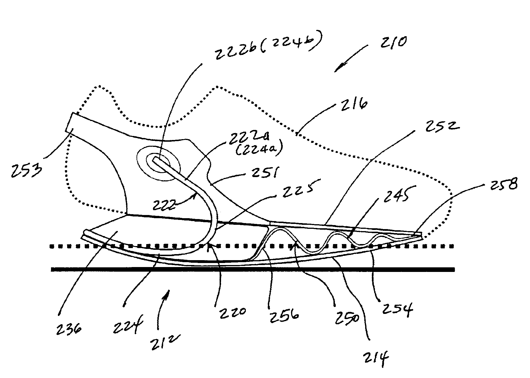
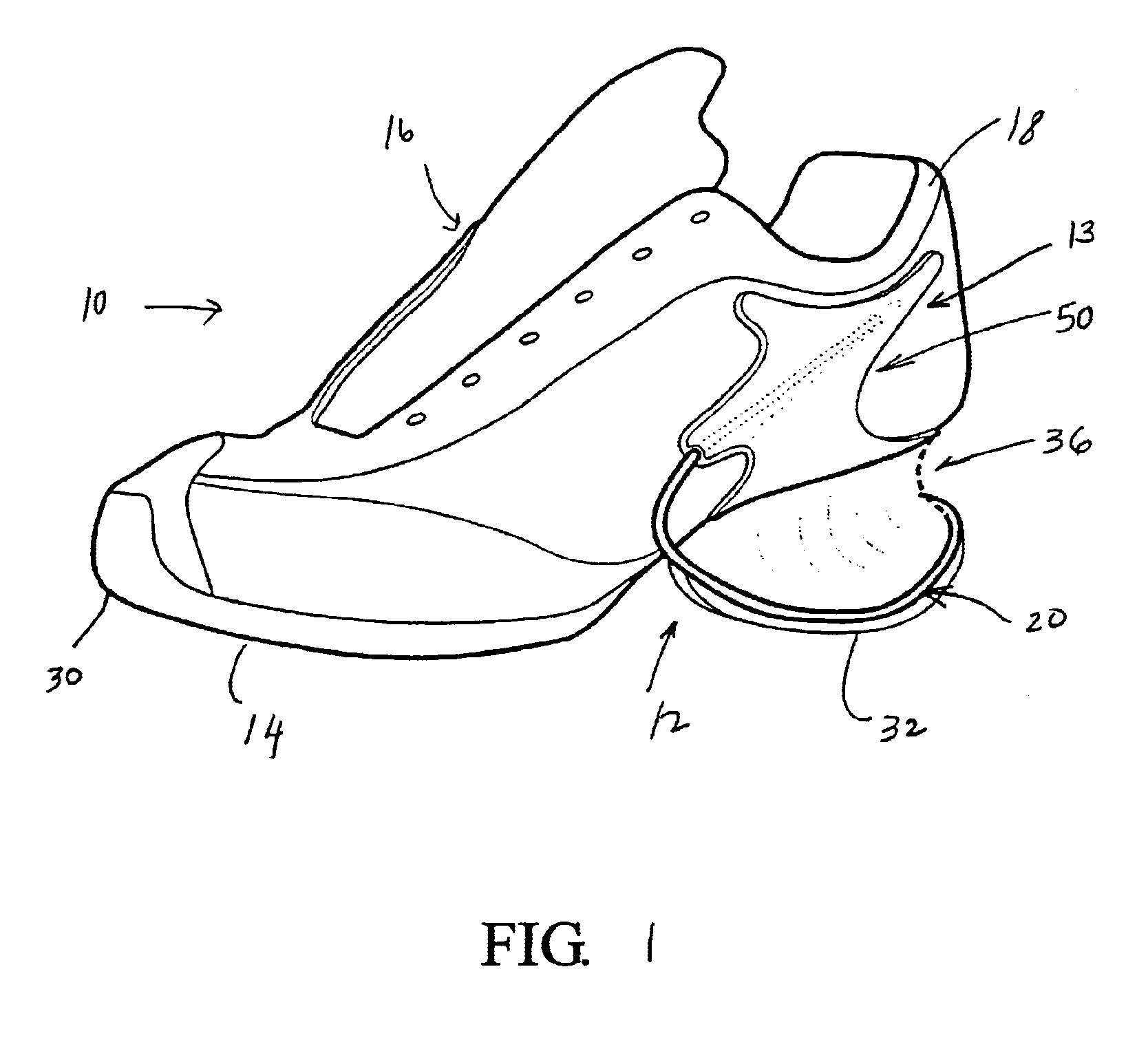
[0049]Referring to FIG. 1, the numeral 10 generally designates a shoe or article of footwear of the present invention. In the illustrated embodiment, footwear 10 comprises an athletic piece of footwear; however, it should be understood that various aspect of the footwear of the present invention may be incorporated into other types of footwear, including therapeutic footwear or everyday use footwear. As will be more fully described below, athletic footwear 10 incorporates an energy storage system 12 that reduces ground impact forces and, further, improves the performance of the user or wearer of the footwear. Optionally and preferably, energy storage system 12 provides a suspension system 13 that reduces the overturning moment forces on the user's ankle to thereby reduce the risk of injury to the wearer by diverting the initial ground reactions forces to a region above the bottom of the heel and, preferably, at or near to ankle joint, where the lateral forces are transferred to the ...


PUM


Abstract

An article of footwear includes a sole, an upper portion, and an energy storage system. The upper portion includes a shell for enclosing a user's foot therein. The energy storage system extends between the upper portion and the sole and converts impact forces generated by the user at the heel portion of the shell into propulsion forces to thereby enhance the user's performance.

Description

[0001]This application is a continuation-in-part of application Ser. No. 09 / 878,021, filed Jun. 8, 2001 now U.S. Pat. No. 6,557,271, which is incorporated by reference herein in its entirety.TECHNICAL FIELD AND BACKGROUND OF THE INVENTION[0002]The present invention generally relates to footwear and, more particularly, to footwear that provides increased stability, cushioning, and, further, that facilitates an enhanced performance for the wearer of the footwear.[0003]When running, a runner's foot transitions through three phases of contact with each stride. Initially, a runner's foot typically lands on its heel. As a result, the heel experiences a significant impact or shock, which is absorbed by the heel bone (calcaneum). Because this is a dynamic force, the impact on the heel can be multiples of the runner's body weight. Furthermore, this impact is transmitted up toward the runner's leg joints.[0004]The second phase initiates when the runner's body weight shifts forward. When the r...

Claims


Application Information

Patent Timeline
Patent Type & Authority Patents(United States)
IPC IPC(8): A43B13/18A43B21/00A43B21/26A43B23/08A43B5/00A43B23/00A43B7/32A43B23/02
CPCA43B3/0063A43B5/00A43B13/18A43B13/183A43B21/26A43B23/08
Inventor WEAVER, III, ROBERT B.
Owner WEAVER III ROBERT B
Why Eureka
Try Eureka