Heart valve holder that resist suture looping

a technology of heart valve and suture loop, which is applied in the field of mitral valve, can solve the problems of deformation of leaflets, damage to annulus or tissue, and difficulty in delivering the prosthetic mitral valve, and achieve the effect of reducing leaflet deformation

Inactive Publication Date: 2005-11-15
EDWARDS LIFESCIENCES CORP
View PDF7 Cites 123 Cited by
  • Summary
  • Abstract
  • Description
  • Claims
  • Application Information

AI Technical Summary

Benefits of technology

[0012]Alternatively, the upstanding member may be solid and include notches for receiving midpoints of the first segments of lengths of flexible material. In this case, each first segment extends from one of the commissure posts radially inward to the upstanding member and then radially outward to an adjacent commissure post via a notch. The upstanding me

Problems solved by technology

In placing a tissue type prosthetic valve in the mitral position, the commissure posts are on the blind side of the valve and may become entangled with pre-installed sutures, and may damage the annulus or tissue during delivery.
The difficulty of the delivery task is compounded if the surgery is through a minimally-invasive access channel, a technique that is becoming more common.
The problem of entanglement is termed “suture looping,” and means that the suture that is used to attach or mount the valve to the heart tissue is inadvertently wrapped around the

Method used


Image

  • Heart valve holder that resist suture looping
  • Heart valve holder that resist suture looping
  • Heart valve holder that resist suture looping

Examples


Embodiment Construction

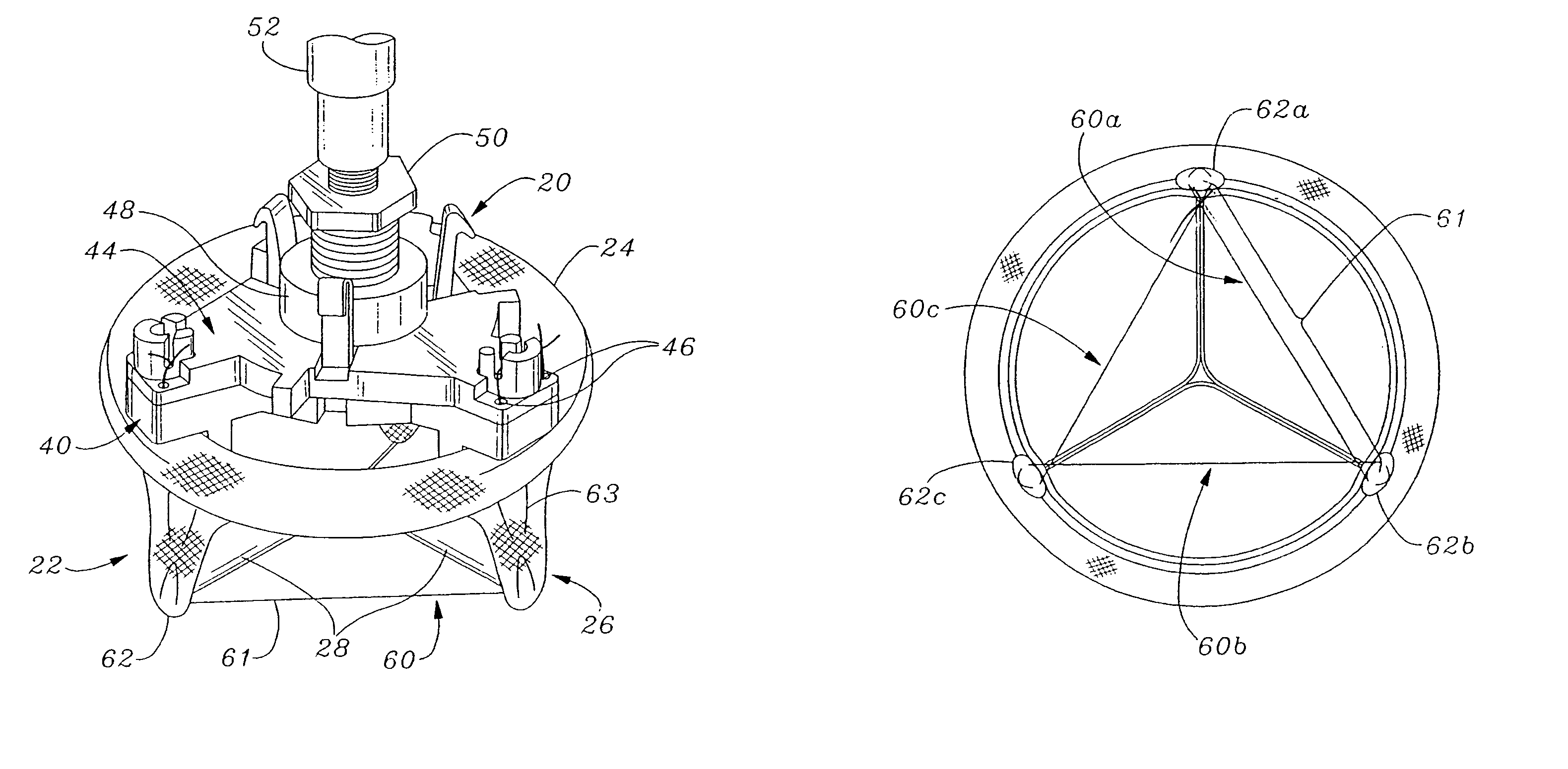
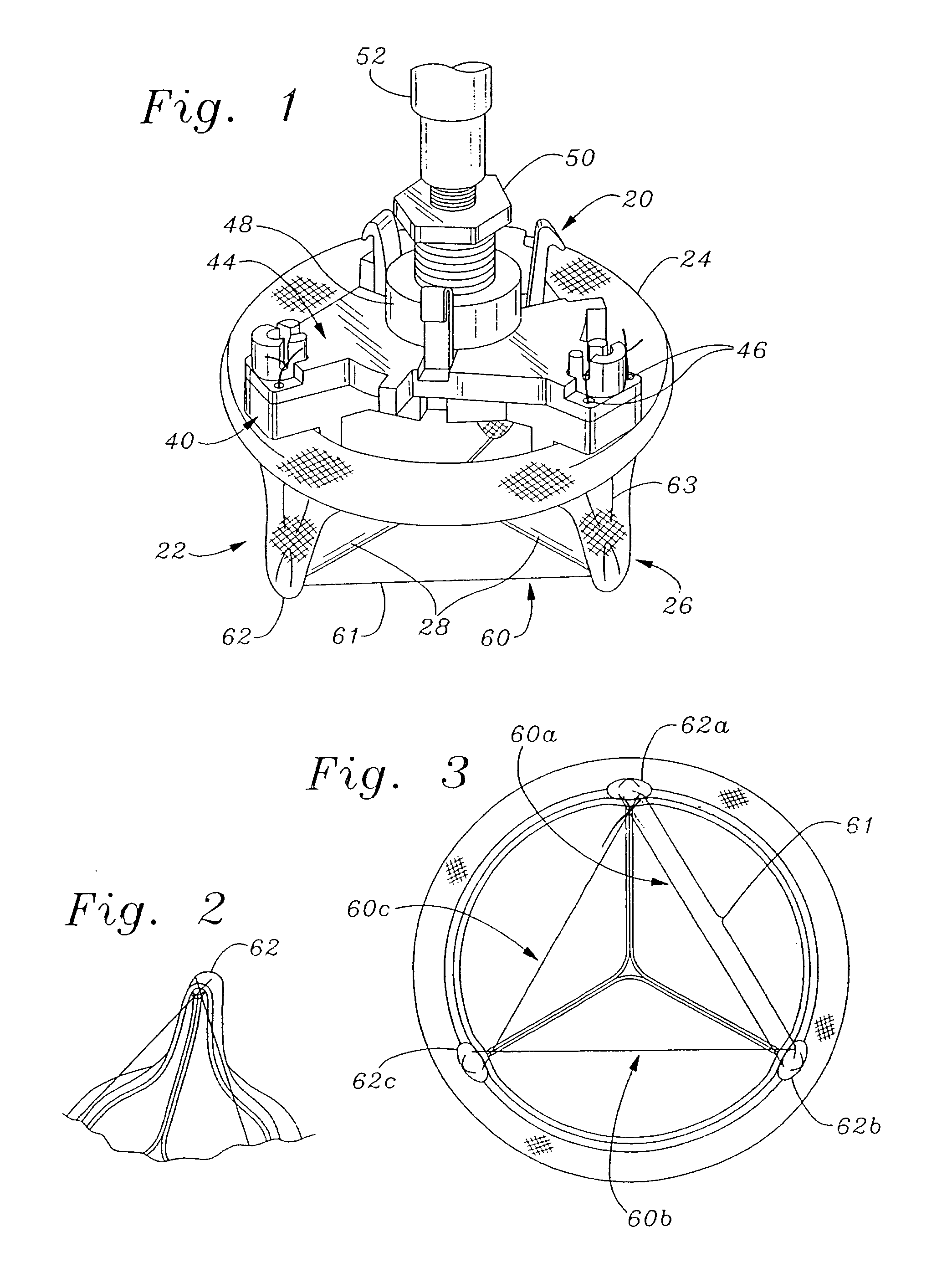
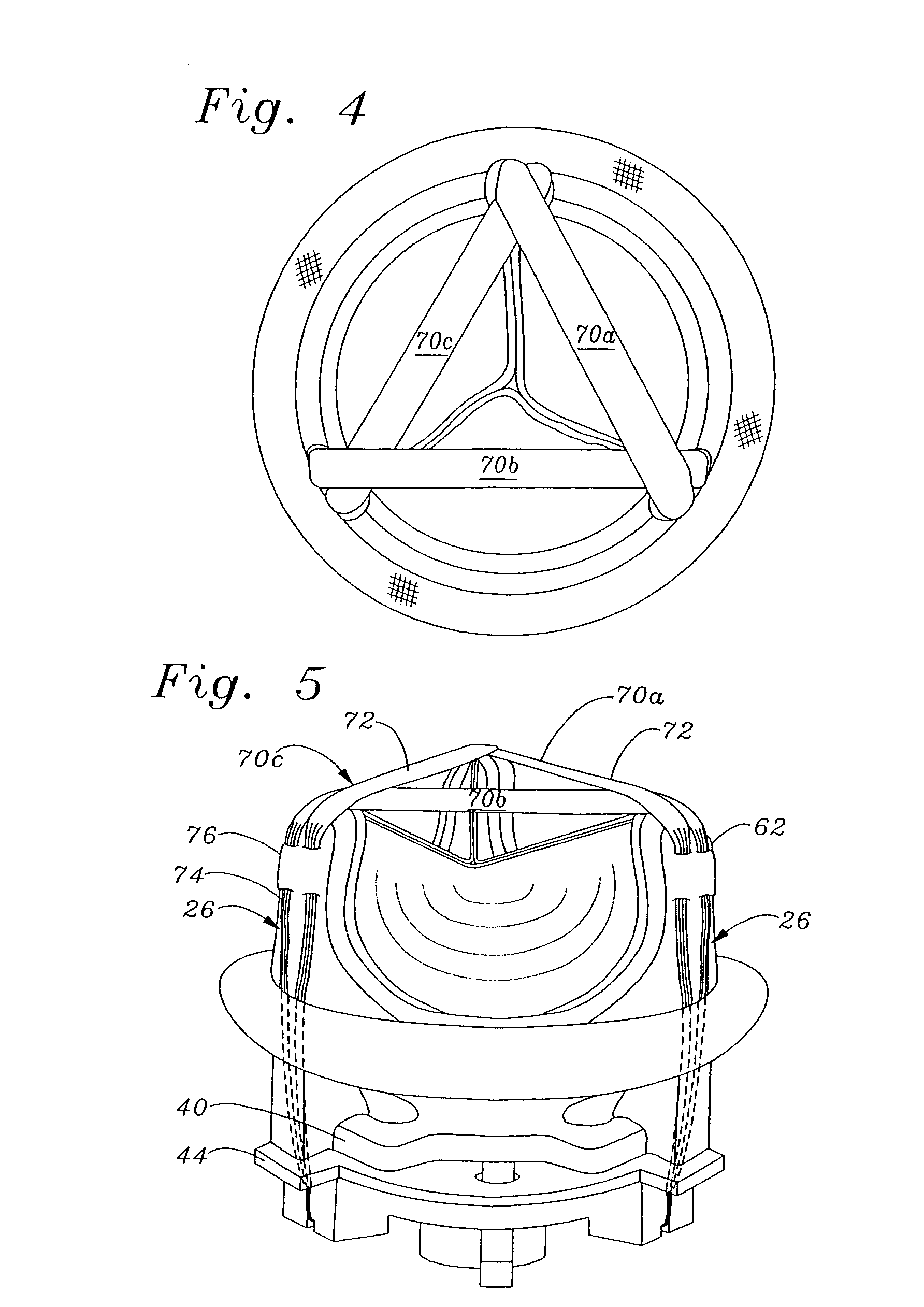
[0027]The present invention provides an improved heart valve holder for tissue-type prosthetic heart valves that facilitates implantation and reduces the chance of suture entanglement. The holder of the present invention is particularly useful for prosthetic mitral heart valves having commissure posts on the outflow side supporting flexible leaflets therebetween. The mitral position is such that the outflow side (and commissure posts) projects distally toward the left ventricle during implantation, and thus the holder must be attached to the inflow (i.e., accessible) side of the valve. Delivery of the valve to the mitral position involves sliding the valve down a plurality or array of sutures that have been pre-installed around the annulus and then passed through the valve sewing ring. The holder of the present invention constricts the commissure posts radially inward and thus helps prevent the posts from becoming entangled in the array of pre-installed sutures. This benefit is thus...


PUM


Abstract

An improved holder, system and method for implanting a tissue-type prosthetic mitral heart valve that prevents suture looping and may also constrict the commissure posts of the valve. The holder may include two relatively movable plates, one of which attaches to the valve sewing on the inflow end of the valve ring and the other which attaches via sutures or similar expedient to the valve commissures on the outflow end. Separation of the plates places the sutures in tension and constricts the commissures. The sutures may be strands or filaments, or may be wider bands of flexible biocompatible material. If bands are used, they desirably cover the commissure post tips to further help prevent suture looping thereover. The flexible lengths of material extend directly between commissures of the valve, or may extending radially inward from each commissure to a central upstanding member. Desirably, a slide is created by the flexible lengths of material adjacent each commissure post, for example by crossing over suture filaments at or radially inward from the commissure posts. If an upstanding member is used, the lengths of suture extend axially beyond the commissure post tips to create a tent that wards off sutures that otherwise might loop around the tips during advancement of the valve along an array of pre-implanted sutures.

Description

FIELD OF THE INVENTION[0001]The present invention relates generally to medical devices, and more particularly to an apparatus for facilitating the implantation of a bioprosthetic replacement heart valve, particularly a mitral valve, and associated methodology.BACKGROUND OF THE INVENTION[0002]In mammalian animals, the heart is a hollow muscular organ having four pumping chambers: the left and right atria and the left and right ventricles, each provided with its own one-way valve. The natural heart valves are identified as the aortic, mitral (or bicuspid), tricuspid and pulmonary valves and have leaflets to control the directional flow of blood through the heart. The valves are each mounted in an annulus that comprises a dense fibrous ring attached either directly or indirectly to the atrial or ventricular muscle fibers. Various surgical techniques may be used to repair a diseased or damaged valve. In a valve replacement operation, the damaged leaflets are excised and the annulus scul...

Claims


Application Information

Patent Timeline
IPC IPC(8): A61F2/24A61F2/48
CPCA61F2/2427A61F2/2412
Inventor NGUYEN-THIEN-NHON, DIANAHOWANEC, JR., MYRONKAFESJIAN, RALPHCOSGROVE, DELOS M.STOBIE, ROBERTLAM, HUNG LY
Owner EDWARDS LIFESCIENCES CORP
Why Eureka
Try Eureka