Rocket motor exhaust scrubber

a scrubber and rocket motor technology, applied in the direction of machine/engine, separation process, dispersed particle separation, etc., can solve the problems of inability to capture and clean the gases emitted by the process, inconvenient use of the scrubber, and insufficient heat generation of the scrubber, so as to reduce the probability of an ignition of combustible gases, effectively capture, cool and remove pollutants, and reduce the temperature of hot exhaust gases.

Inactive Publication Date: 2005-11-15
THE UNITED STATES OF AMERICA AS REPRESENTED BY THE SECRETARY OF THE NAVY
View PDF15 Cites 48 Cited by
  • Summary
  • Abstract
  • Description
  • Claims
  • Application Information

AI Technical Summary

Benefits of technology

[0019]It is still further an object of the present invention to provide a device that significantly reduces the probability of an ignition of the combustible gases from a static discharge.
[0020]According to the present invention, the above-described and other objects are accomplished by providing a rocket motor exhaust scrubber that cleans the motor exhaust while the motor is firing. The rocket motor is instrumented and located to fire directly into the present invention, which is a wet scrubber. The motor gases are vigorously sprayed with a solution of water with caustic KOH additive. The spray cools the gases from 3500 F to 195 F, agglomerates the solids, and captures and neutralizes the HCl gases formed when the composite type propellant is burned. The liquids and solids are removed by passing the wet, dirty gases through a mesh style demister, and then the cleaned gases are released to the atmosphere. The device effectively captures, cools, and removes pollutants from exhaust gas streams generated when rocket motors are test fired. The scrubber comprises a first chamber for capturing exhaust gases which consists of a quench chamber where spray nozzles inject the caustic spray solution. The temperature of the hot exhaust gases is quickly reduced, and the primary combustion product, gaseous HCL, is condensed and absorbed by the caustic solution. The remaining exhaust products (such as Al2 O3, CO, Pb, etc.) exit the quench chamber either in a liquid slurry or a cool wet gas, and enter a demister chamber. In the demister vessel, a spray system again scrubs the gasses by spraying caustic solution through the gas stream as it passes upward and through the vessel. A mesh-style demister at the top of the vessel intercepts and captures the liquid and solid particles, and the resulting clean and dry gases (e.g., mist-free or liquid free gases) are accelerated through a centrifugal fan into the atmosphere. The fan at the discharge creates a forced ventilation system that provides a continuous flow of air so that when the rocket motor fires there is already a system flow path and the exhaust is “guided” into the scrubber. This eliminates any pressure rise at the end of firing when the rocket motor exhaust gas velocity head is converted into static pressure, and it provides a means of purging the exhaust gases between motor firings. The forced flow also pre-wets all of the steel internals with spray solution prior to igniting the motor, and also prepares the mesh demister for operation. The forced ventilation system also inhales and scrubs the last small vestiges of propellant which continue to burn for several seconds after the motor firing, and eliminates the acrid smell present for minutes after firing (the fumes causing the odor are also an irritant to operators). Containing and scrubbing all of the exhaust gases also eliminates particulates in the immediate firing area that can contaminate surface water runoff.

Problems solved by technology

The Mak '317 process is a continuous flow process and is not suitable for use with rocket motors.
The process is not designed to capture and clean gases emitted at the high velocities attained by rocket motor exhaust gases.
Scrubbing rocket motor gases poses unique challenges because the gases emitted are very hot, reaching temperatures of 3500 degrees Fahrenheit, and are expelled at very high velocities, averaging up to 2900 ft / sec.
Furthermore most industrial scrubbers are not concerned with avoiding any performance impact on a rocket motor being fired into the scrubber.
However, this scrubber was very intrusive and did not measure the thrust and performance capabilities of the rocket being tested.
Significantly, the Edwards scrubber employed a static ventilation flow path which causes a pressure rise at the end of firing when the rocket motor exhaust gas velocity head is converted into static pressure, which induces back pressure on the rocket motor providing an less accurate thrust measurement.
In addition, the Edwards scrubber caused a potential for ignition of the H2 and CO in the rocket exhaust.
After a rocket motor fires there is nearly always a flammable quantity of these gases present, and when the exhaust gases combine / mix with the ambient air already in the scrubbed or added air, a serious potential for ignition exists.
The Edwards scrubber was also prone to overpressure, and secondary combustion of the exhaust gases.
These pressures and temperatures caused problems as it exceeded the physical limits of the scrubber.
Also, the Edwards scrubber made no provisions for recycling the spray solution.
Aside from the foregoing, there also are a number of existing high altitude test chambers at Arnold Air Force Base that capture and provide some “washing” of gases with cooling water, but these are high altitude testing chambers and are not well-suited for production testing of rocket motors.
There currently are no known existing rocket motor exhaust scrubbers capable of accurately, safely, and economically measuring thrust in an environmentally acceptable manner.

Method used


Image

  • Rocket motor exhaust scrubber
  • Rocket motor exhaust scrubber
  • Rocket motor exhaust scrubber

Examples


Embodiment Construction

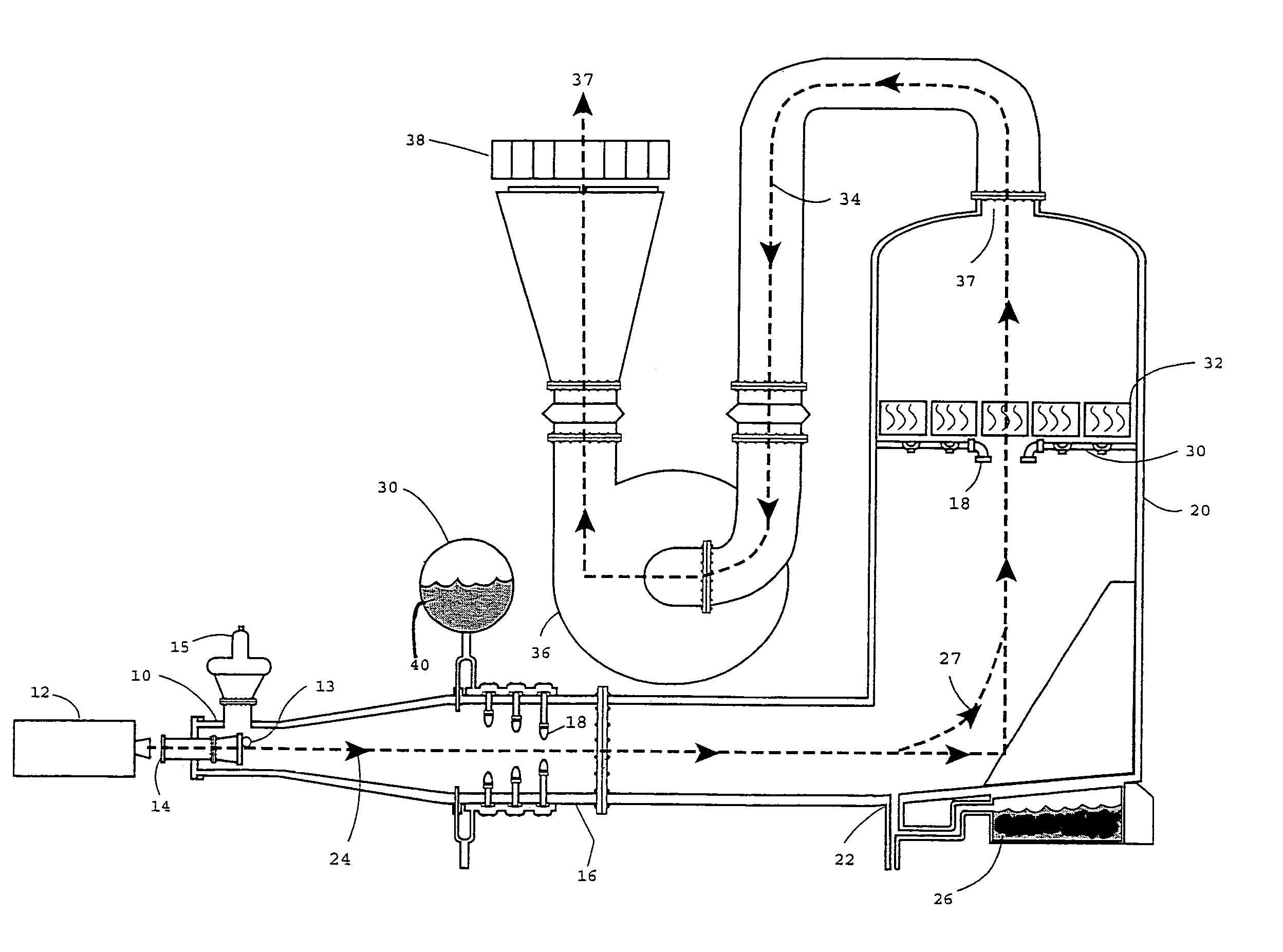
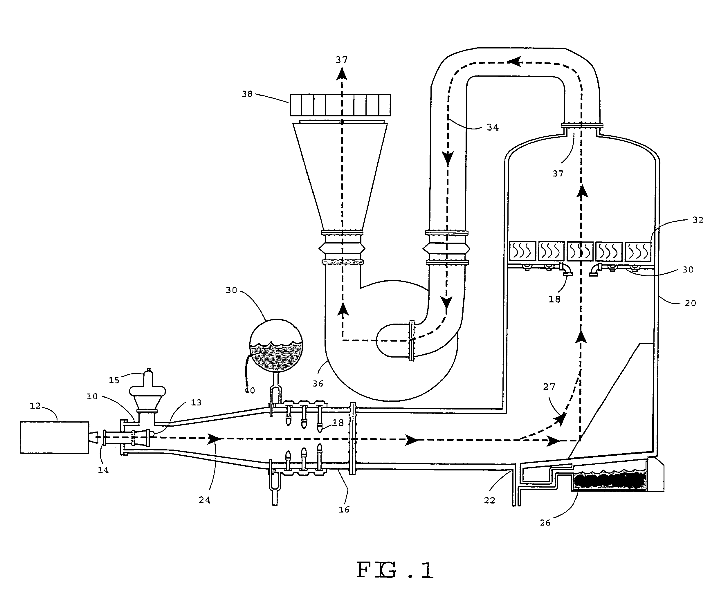
[0024]FIG. 1 is a side perspective schematic view of the rocket motor exhaust scrubber 10 according to the present invention. A test rocket motor 12 is secured adjacent to an inlet 14 in scrubber 10. Inlet 14 is a hollow cylindrical chamber for transporting exhaust gases 24 from rocket motor 12 into scrubber 10. The inlet 14 is preferably a tube that is approximately 12″ long, and completely enclosed inside the scrubber 10, although one skilled in the art will understand that the exact length and diameter of inlet 14 are dependent on the nozzle and plume of the firing motor nozzle.

[0025]Motor 12 is situated such that it does not touch inlet 14, but is close enough that it captures exhaust gases 24 when the rocket motor is fired. This is accomplished by sizing the diameter of inlet 14 in accordance with the spacing between motor 12 and inlet 14 so that the motor plume will expand to the inner diameter of the inlet 14 before entering the scrubber 10 (expansion characteristics for the ...


PUM

PropertyMeasurementUnit
velocityaaaaaaaaaa
velocitiesaaaaaaaaaa
temperaturesaaaaaaaaaa

Abstract

A wet scrubber having a series of chambers for capturing and cooling exhaust gases generated during static test firing of rocket motors. Exhaust gas enters an inlet to a first chamber and is cooled and slowed by a spray solution. HCL gas is condensed and absorbed by the spray solution and precipitates to a liquid slurry at the bottom of the device. The remaining exhaust products enter a demister chamber where nozzles continue to spray the gasses as they pass upward and through a mesh-style demister at the top of the vessel. The demister filters liquid and solid waste particles from the gas stream, and the clean, dry gases are accelerated through a centrifugal fan into the atmosphere. A deflector is positioned within the inlet to the first chamber for containing parts in the event of a motor mal-function.

Description

STATEMENT OF GOVERNMENT INTEREST[0001]The invention described herein may be manufactured and used by or for the Government of the United States of America for governmental purposes without payment of any royalties thereon or therefor.BACKGROUND OF THE INVENTION[0002]1. Field of the invention[0003]The present invention relates to an apparatus for scrubbing exhaust gases, and more particularly to a scrubber for removing waste gases from exhaust generated when rocket motors are test fired, in a manner that is both environmentally compliant and economically acceptable.[0004]2. Description of the Background[0005]The United States Department of Defense test fires thousands of rocket motors each year for lot acceptance testing, rocket motor development, and surveillance testing of fleet returned motors. Rockets range in size up to 1,000,000 pounds (propellant weight). Test firing these rockets produces tons of gaseous products every year, most of which is of concern to the Environmental Pr...

Claims


Application Information

Patent Timeline
Patent Type & Authority Patents(United States)
IPC IPC(8): B01D47/00B01D53/14B01D53/68
CPCB01D53/68B01D2251/604B01D2257/2045B01D2257/60
Inventor CARNS, RICHARD H.ARMSTRONG, GERALDRAST, ROBERT H.MITCHELL, DENNIS R.
Owner THE UNITED STATES OF AMERICA AS REPRESENTED BY THE SECRETARY OF THE NAVY
Why Eureka
Try Eureka