Integrated bypass turbojet engines for air craft and other vehicles

a bypass turbojet and air craft technology, applied in the field of turbojet engines, can solve the problems of reducing the thermal efficiency of conventional turbojets, the complexity of modern turbojets has reached the maximum level, and the cost is beyond the affordability limit of the majority of the world, so as to achieve the effect of reducing complexity, weight, cost and maximizing the absolute thermal energy capacity and thermal efficiency

Inactive Publication Date: 2005-11-22
PAUL MARIUS A
View PDF16 Cites 97 Cited by
  • Summary
  • Abstract
  • Description
  • Claims
  • Application Information

AI Technical Summary

Benefits of technology

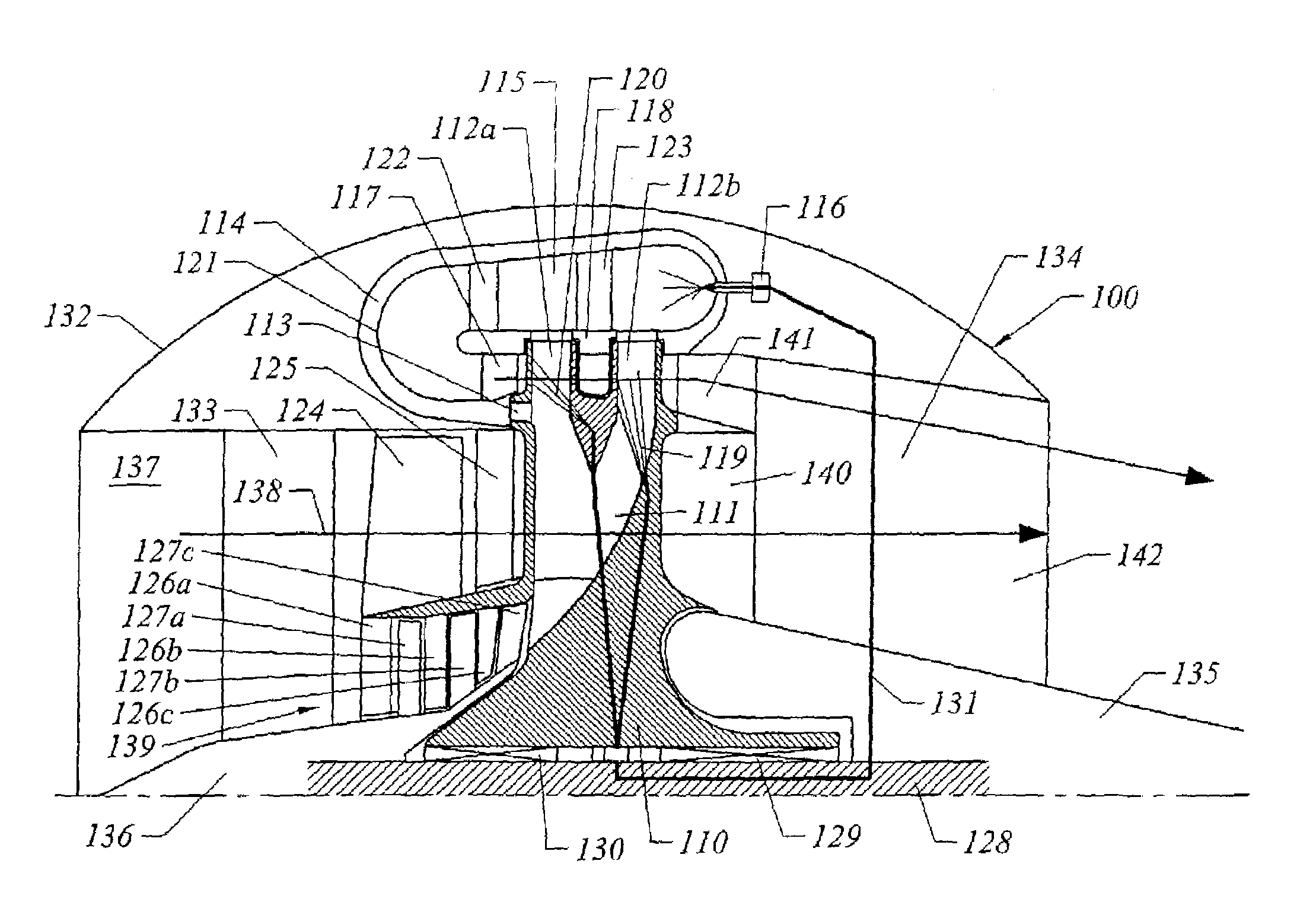
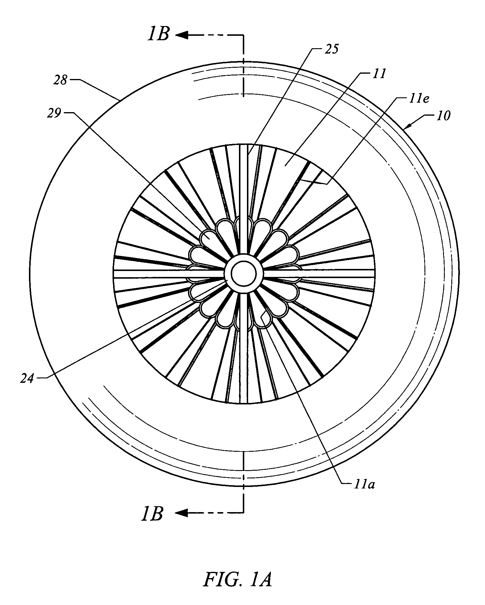
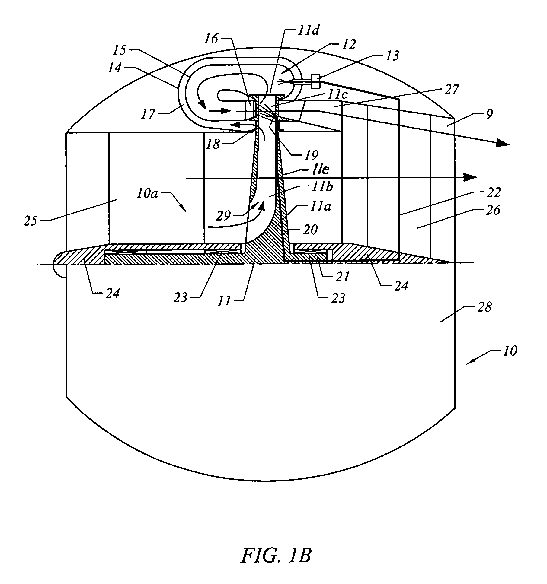
[0013]This integration of modules results in a massive reduction in complexity, weight, cost and overall dimensions of the propulsion unit. This reduction is associated with a maximization of the absolute thermal energetic capacity and thermal efficiency by the ability to work at the stoichiometric level. This ability is the result of internally cooling the turbine blades by cool isothermically compressed air that is centrifugally compressed within the hollow fan blades and is cooled by intake air flowing between the fan blades, and in certain embodiments by fuel injected inside of the turbine blades.

Problems solved by technology

The complexity of modern turbo jets has reached the maximum level, and the cost is beyond any limit of affordability by the majority of the world.
The thermal efficiency of conventional turbojets is limited to 30% at full loads and drops to near 10% at part loads.
The power density is limited by the maximum temperature of the combustion.
At 25% of the maximum stoichiometric level, the air fuel ratio is 60 / 1, instead of a stoichiometric 15 / 1, making all turbojet engines at least four times larger than an engine operating at the stoichiometric level, with a resulting lower efficiency and greater expense.
For military applications, specifically drone airplanes and cruise missiles, the high cost for aircraft designed to be lost in combat is a major expense for defense and a burden on the national economy.
The greatest barriers for high performance gas turbines and jet engines are the limitations on maximum temperature acceptable for combustion gases and the limitations in the pressure ratio of air compression in the engine cycle.
The metallurgical properties of gas turbine blades and the limited cooling schemes available for gas turbine blades combine to severely limit turbine inlet temperatures.

Method used


Image

  • Integrated bypass turbojet engines for air craft and other vehicles
  • Integrated bypass turbojet engines for air craft and other vehicles
  • Integrated bypass turbojet engines for air craft and other vehicles

Examples


first embodiment

[0085]In FIG. 8 there is depicted a fifth application of the turbojet engine 10 for a VTOL wing vehicle 80 in which the integrated turbo by-pass jet 81, described in the invention, is located in the front of the VTOL wing vehicle 80. The VTOL (vertical takeoff or landing) wing vehicle 80 has an intake channel 82, completely masked in the front profile of the fuselage for radar avoidance. Air-gas propulsion is diverted from a central channel 83 to a right channel 84 and a left channel 85 by the variable deflectors ports 86a and 86b. Transverse perpendicular openings 87a and 87b direct the selectively diverted airgas flow to each side of the wings for up or down discharge relative to the surface of the wing. The variably directed central exit 88 at the aircraft tail directs the main flow of air-gas and vector of jet propulsion axially in the main direction, or perpendicular to the face of the wing in either direction, up or down. The auxiliary wing panels 89a, 89b, 90a, 90b, 91a and 9...

embodiment 700

[0151]Referring to the embodiment in FIG. 32, the high altitude turbojet engine indicated generally by the number 750, is a derivative solution from the embodiment 700 of FIG. 31. The turbojet engine has a body 751, includes all the ram-air frontal components of the FIG. 31, but including a second ram-air turbine 752, having hollowed blades acting as a final isothermal centrifugal compressor 753 supplying compressed air through hollowed struts 754, conducting the cooled air to a central combustion chamber 755, surrounded by an air plenum 756, spaced from a combustion chamber liner 758, which is preferably made from ceramic.

[0152]The combusted jet rocket gases are controlled by a variable geometry exit nozzle 759, 760, optimizing a constant pressure ration for combustion at all speeds, which in turn conserves the maximum thermal efficiency during all regimes of flight.

[0153]The rocket gas jet 761 is finally mixed with by-pass air flow jet 762, forming the final combined propulsion je...

third embodiment

[0155]Referring to FIG. 33, the high altitude turbojet engine is designated generally by the reference numeral 800. The turbojet engine 800 has forward components that are the same as in the engine 750 with different internal aft components forming a central combustion system 802 for convertible turbine / rocket propulsion. In FIGS. 33 and 34 the ram-air turbine 752 and final isothermal centrifugal compressor 753 supply compressed air through first air passages 803 in the hollowed struts 754 and by-pass passage 805 around the struts 754.

[0156]As shown in greater detail in FIG. 34, the air passage 803 in the struts 754 divides into three channel 806, 807 and 808 formed by a concentric peripheral air plenum 810, a concentric internal air plenum 811, and an interposed perforated annular combustion chamber 812 concentric with the peripheral and internal air plenums 810 and 811. Fuel injectors 814 inject fuel into the annular combustion chamber 812 for generating combustion gases which pro...


PUM


Abstract

Turbojet engines and aircraft configurations for advantageous use of the turbojet engines; the turbojet engines utilizing ram air turbine units that centrifugally compress air isothermally for use in various combustion configurations designed for stoichiometric combustion, wherein a stream of by-pass ram-air jets is mixed with combustion gas jets for discharge in a common discharge nozzle.

Description

[0001]This application is a continuation-in-part of applications, U.S. Ser. No. 10 / 337,032 filed on Jan. 6, 2003, and U.S. Ser. No. 10 / 292,829 filed on Nov. 12, 2002.[0002]This application claims the benefit of the following provisional applications: U.S. Ser. No. 60 / 372,618 filed on Apr. 15, 2002; U.S. Ser. No. 60 / 374,737 filed on Apr. 23, 2002; U.S. Ser. No. 60 / 405,460 filed on Aug. 23, 2002.BACKGROUND OF THE INVENTION[0003]This invention relates to a new category of turbojet engines and the application of turbojet engines to aircraft and other vehicles. The turbojet engines are of a type in which the bypass fan blades are integrated with the compressor in association with the turbine blades that are surrounded by an annular combustion chamber. The turbojet engines of this invention are improvements over the engines described in my U.S. Pat. No. 4,845,941 entitled “Gas Turbine Engine Operating Process”, issued Jul. 11, 1989, my U.S. Pat. No. 5,003,766 entitled “Gas Turbine Engine”...

Claims


Application Information

Patent Timeline
Patent Type & Authority Patents(United States)
IPC IPC(8): B64D27/16B64C29/00B64D27/00F02C3/00F02C3/045F02K3/077F02C3/08F02K3/00F02K3/02F02K3/04
CPCB64C29/0075B64D27/16F02C3/045F02C3/08F02K3/04F02K3/077F02K3/02Y02T50/671Y02T50/44Y02T50/40Y02T50/60
Inventor PAUL, MARIUS A.
Owner PAUL MARIUS A
Why Eureka
Try Eureka