Microstrip-to-waveguide power combiner for radio frequency power combining

a power combiner and microstrip technology, applied in the micro field, can solve the problems of large loss, large volume of summing network, and high precision components, and achieve the effects of low loss, small “real estate” and power efficiency

Inactive Publication Date: 2005-11-22
REVEAL IMAGING
View PDF24 Cites 35 Cited by
  • Summary
  • Abstract
  • Description
  • Claims
  • Application Information

AI Technical Summary

Benefits of technology

[0009]It is therefore an object of the present invention to provide a microstrip-to-waveguide and a coaxial-to-waveguide power combiners that

Problems solved by technology

Although this type of power combining is efficient, the summing network is generally bulky and requires very high precision components.
This type of power combining circuit is more simple to implement in practice, but generally has higher losses.
The precision requirements for this waveguide and the requirement for a metal coating on the inside surface of the waveguide to achieve low losses results in r

Method used


Image

  • Microstrip-to-waveguide power combiner for radio frequency power combining
  • Microstrip-to-waveguide power combiner for radio frequency power combining
  • Microstrip-to-waveguide power combiner for radio frequency power combining

Examples


Embodiment Construction

[0033]The present invention will now be described more fully hereinafter with reference to the accompanying drawings, in which preferred embodiments of the invention are shown. This invention may, however, be embodied in many different forms and should not be construed as limited to the embodiments set forth herein. Rather, these embodiments are provided so that this disclosure will be thorough and complete, and will fully convey the scope of the invention to those skilled in the art. Like numbers refer to like elements throughout.

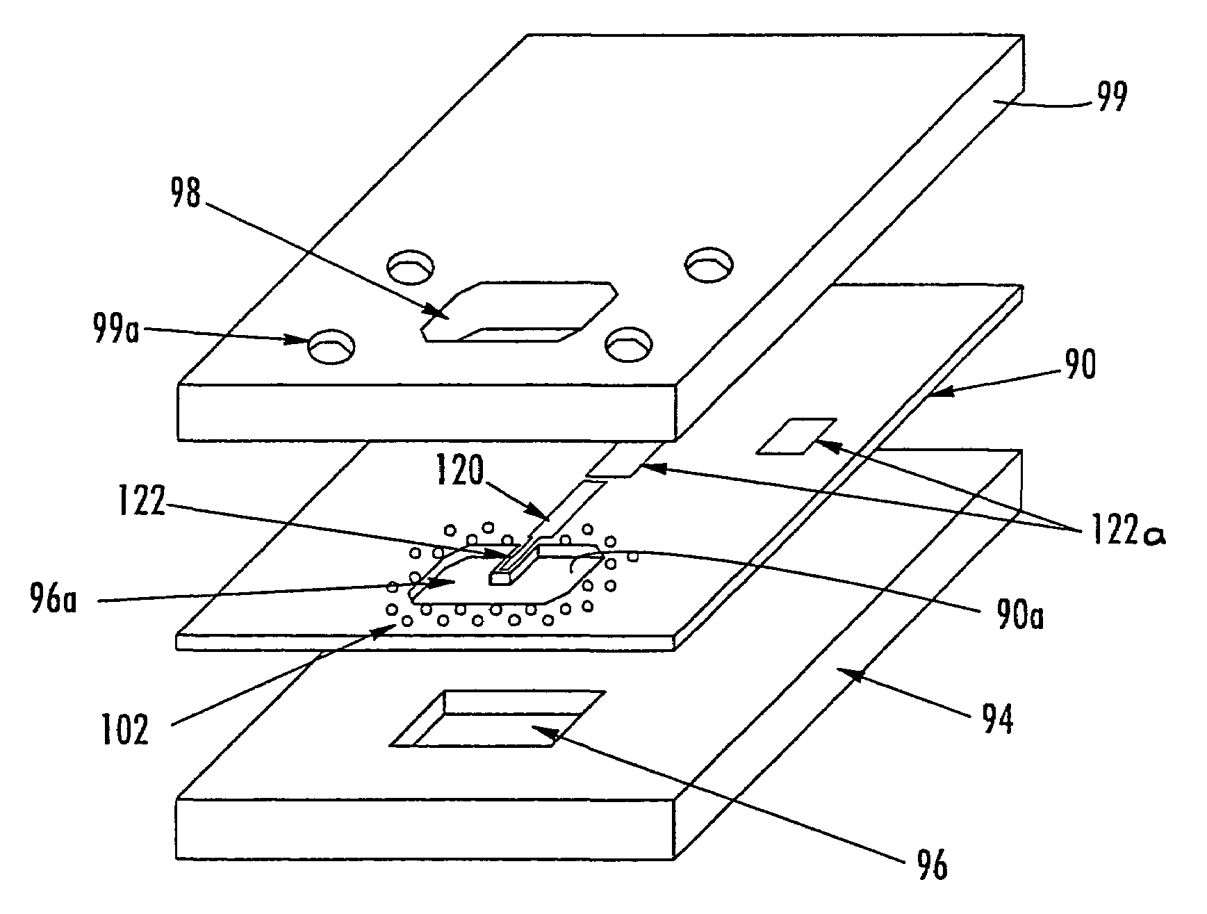
[0034]The present invention is advantageous and power combines radio frequency signals using a combination of microstrip and waveguide or coax and waveguide techniques that result in very low losses. The power combining network of the present invention is extremely compact and can be used at a very low cost. In the present invention, two or more sources of radio frequency energy can be combined in a microstrip-to-waveguide or coax-to-waveguide transitions ...


PUM


Abstract

A microstrip-to-waveguide power combiner includes a dielectric substrate and at least two microstrip transmission lines formed thereon in which radio frequency signals are transmitted. The microstrip transmission lines terminate in microstrip launchers or probes at a microstrip-to-waveguide transition. A waveguide opening is positioned at the transition. A waveguide back-short is positioned opposite the waveguide opening at the transition. Isolation vias are formed within the dielectric substrate and around the transition and isolate the transition. A coaxial-to-waveguide power combiner is also disclosed.

Description

RELATED APPLICATION[0001]This application is a continuation of Ser. No. 10 / 218,669 filed Aug. 14, 2002. Now U.S. Pat. No. 6,707,348 which is based on provisional patent application Ser. No. 60 / 374,712 filed Apr. 23, 2002, the disclosure of which is hereby incorporated by reference in its entirety.FIELD OF THE INVENTION[0002]This invention relates to power combining radio frequency signals, and more particularly, this invention relates to a power combining network for combining radio frequency signals using microstrip and waveguide circuits.BACKGROUND OF THE INVENTION[0003]Power combining techniques for radio frequency signals, including millimeter wavelength signals, have been accomplished in either a waveguide circuit or in a microstrip circuit. For example, prior art waveguide combining has been accomplished by feeding two or more signals in phase into a waveguide combiner. Although this type of power combining is efficient, the summing network is generally bulky and requires very...

Claims


Application Information

Patent Timeline
IPC IPC(8): H01P5/103H01P5/12H01P5/107H01P5/10
CPCH01P5/103H01P5/107H01P5/12
Inventor AMMAR, DANNY F.
Owner REVEAL IMAGING
Why Eureka
Try Eureka