Data converters with digitally filtered pulse width modulation output stages and methods and systems using the same

a data converter and pulse width modulation technology, applied in digital-analog convertors, transmission systems, instruments, etc., can solve the problems of significant drawbacks of continuous-time output stages and susceptibility to inter-symbolic interference, and achieve the effect of reducing distortion, reducing susceptibility to isi and clock vagaries

Inactive Publication Date: 2005-11-22
CIRRUS LOGIC INC
View PDF2 Cites 27 Cited by
  • Summary
  • Abstract
  • Description
  • Claims
  • Application Information

AI Technical Summary

Benefits of technology

[0009]Application of the present inventive principles provides for the design and construction of digital data converters, in particular DACs, utilizing continuous-time output elements with minimal susceptibility to ISI and clock vagaries. Generally, a duty-cycle modulator receives a digital input stream and generates a duty-cycle, pulse width modulated (PWM) encoded data stream. A finite impulse response (FIR) filter removes the fundamental frequency and harmonics of the PWM rate from the duty cycle modulated stream. By tapping the stages of the FIR filter with a plurality of digital to analog conversion elements, in either a continuous-time or discrete-time manner, an analog output signal is generated with reduced distortion due to jitter of ISI. In one particular embodiment, multiple pulse width modulator stages are interleaved in time to generate multiple time-overlapping PWM-encoded data streams. These overlapping PWM-encoded data streams drive multiple conversion elements with matched utilization and transition rates. A delta-sigma modulator with multiple attenuation bands in front of the interleaved PWM stages attenuates noise that would otherwise be demodulated by mismatch between the analog stages. A FIR filter coupled after each interleaved PWM stage removes out of band energy caused by the PWM process.

Problems solved by technology

Despite their advantages, continuous-time output stages are also subject to significant drawbacks, such as a susceptibility to inter-symbol interference.

Method used


Image

  • Data converters with digitally filtered pulse width modulation output stages and methods and systems using the same
  • Data converters with digitally filtered pulse width modulation output stages and methods and systems using the same
  • Data converters with digitally filtered pulse width modulation output stages and methods and systems using the same

Examples


Embodiment Construction

[0019]The principles of the present invention and their advantages are best understood by referring to the illustrated embodiment depicted in FIGS. 1–5 of the drawings, in which like numbers designate like parts.

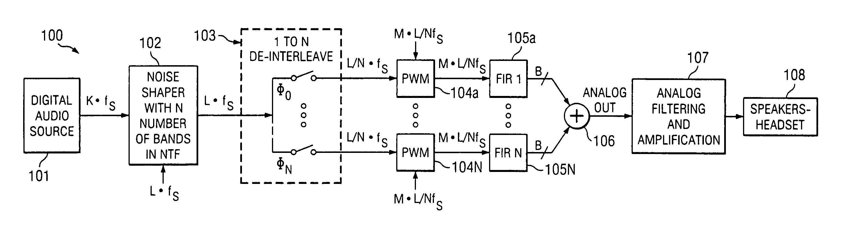
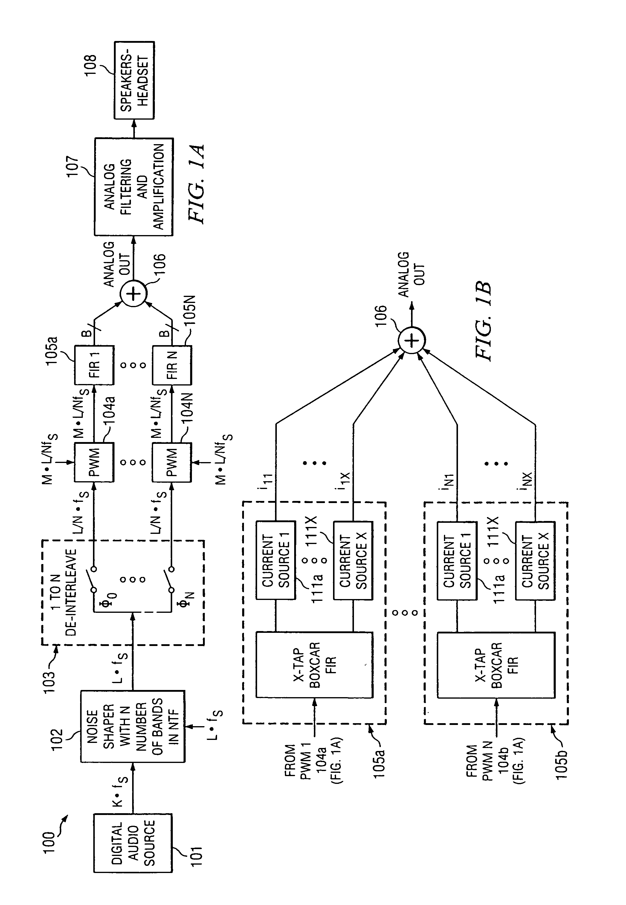
[0020]FIG. 1A is a high-level functional block diagram of an exemplary digital to analog converter system 100 suitable for demonstrating the principles of the present invention. For purposes of discussion, an audio application is described operating on digital audio from a source 101 such as a compact disk (CD) or digital versatile disk (DVD) player; however, the concepts described below can be utilized in a wide range of circuits and systems requiring digital to analog conversion. In system 100, the data output from digital source 101 is multiple-bit audio data having a base sampling frequency (rate) fs and oversampled by an oversampling factor K. For example, in the illustrated embodiment the audio stream is output from digital audio source 101 with a base sampling frequen...


PUM


Abstract

A digital to analog converter including a noise shaping modulator for modulating an input digital data stream, a plurality of output elements for generating a plurality of intermediate data streams from a modulated output stream from the modulator, and an output summer for summing the intermediate data streams to generate an output analog stream. The noise shaping modulator balances an edge transition rate of the output elements, such that the edge transition rate of two selected elements is approximately equal.

Description

CROSS-REFERENCE TO RELATED APPLICATION[0001]This application is a continuation of U.S. Ser. No. 10 / 306,598 filed on Nov. 27, 2002 which is now U.S. Pat. No. 6,727,832, entitled “DATA CONVERTERS WITH DIGITALLY FILTERED PULSE WIDTH MODULATION OUTPUT STAGES AND METHODS AND SYSTEMS USING THE SAME” by inventor Melanson, currently allowed, and is incorporated herein by reference.FIELD OF INVENTION[0002]The present invention relates in general to delta-sigma data converters, and, in particular, to data converters with digitally filtered pulse width modulation output stages and methods and systems using the same.BACKGROUND OF INVENTION[0003]Delta-sigma modulators are particularly useful in digital to analog and analog to digital converters (DACs and ADCs). Using oversampling, the delta-sigma modulator spreads the quantization noise power across the oversampling frequency band, which is typically much greater than the input signal bandwidth. Additionally, the delta-sigma modulator performs n...

Claims


Application Information

Patent Timeline
Patent Type & Authority Patents(United States)
IPC IPC(8): H03M3/00
CPCH03M3/372H03M3/506
Inventor MELANSON, JOHN LAURENCE
Owner CIRRUS LOGIC INC
Why Eureka
Try Eureka