Multi-component induction instrument

a multi-component induction instrument technology, applied in the field of induction resistivity measurement, can solve the problems of inconsistency of data logs obtained with a conventional transversal induction logging instrument, difficult detection of hydrocarbon-bearing zones,

Inactive Publication Date: 2003-02-06
BAKER HUGHES INC
View PDF0 Cites 21 Cited by
  • Summary
  • Abstract
  • Description
  • Claims
  • Application Information

AI Technical Summary

Problems solved by technology

In general, when using a conventional induction logging tool with transmitters and receivers (induction coils) having their magnetic moments oriented only along the borehole axis, the hydrocarbon-bearing zones are difficult to detect when they occur in multi-layered or laminated reservoirs.
These reservoirs usually consist of thin alternating layers of shale and sand and, oftentimes, the layers are so thin that due to the insufficient resolution of the conventional logging tool they cannot be detected individually.
One of the main difficulties in interpreting the data acquired by a transversal induction logging tool is associated with its response vulnerability of to borehole conditions.
However, even with these modifications, the data logs obtained with a conventional transversal induction logging instruments can be inconsistent, difficult to interpret, and the problems have been exacerbated while logging through a sequence of layers.
However, the presence of conductive bodies typically fo...

Method used


Image

  • Multi-component induction instrument
  • Multi-component induction instrument
  • Multi-component induction instrument

Examples


Embodiment Construction

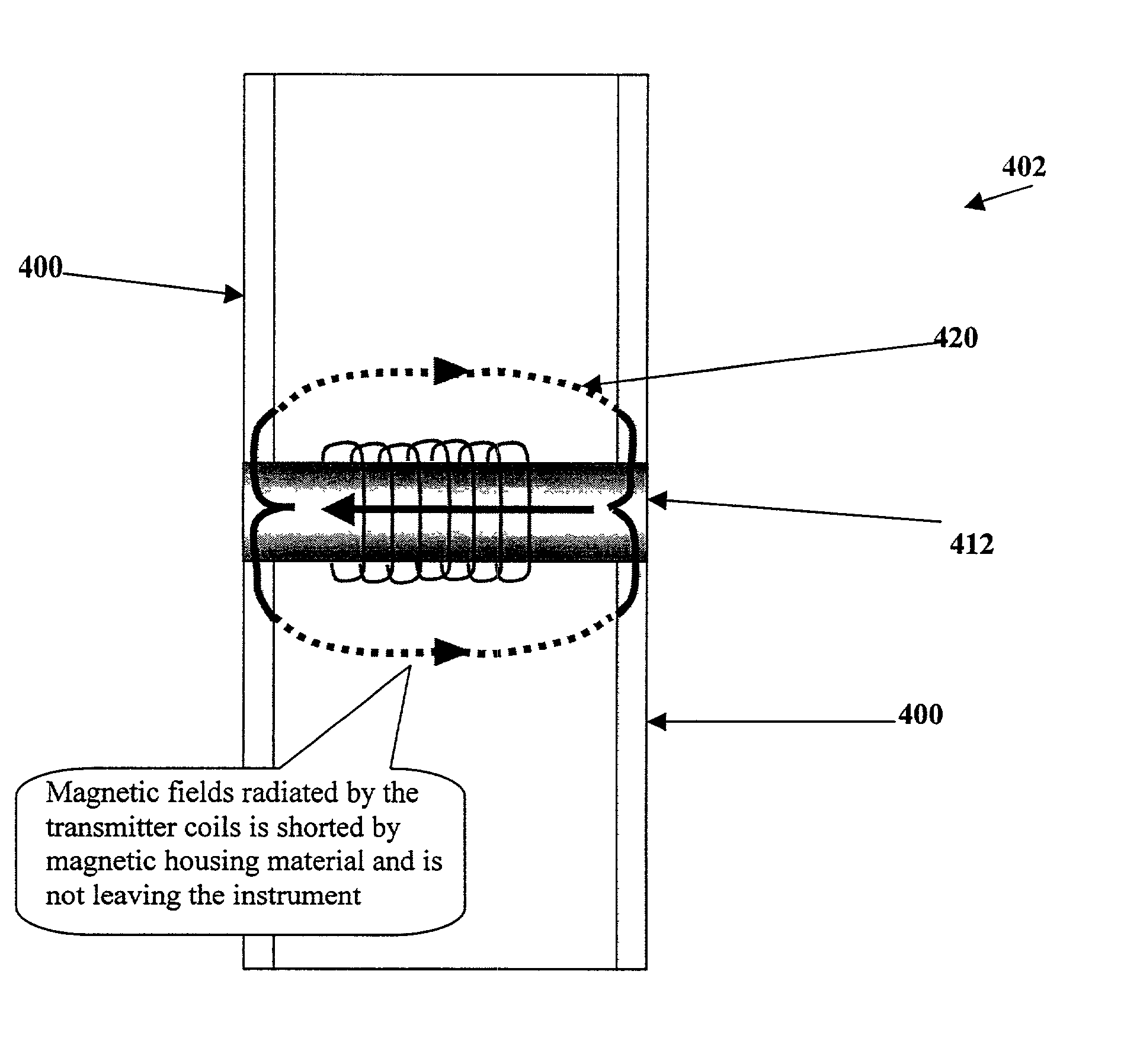
[0026] The transmitter and receiver coil geometric areas together with the transmitter current define a total magnetic moment of an induction tool. By design, these coils are built preferably with an effective geometrical area sufficiently large to achieve the maximum possible random noise-free measurements while using conventional amounts of electrical power available to MWD equipment. A coil geometric area would be sufficiently large when non-productive losses that may occur while generating the primary magnetic field or detecting the secondary magnetic field flux induced from the formation are either adequately compensated for or properly accounted for. In many circumstances these limitations can be evaluated from the basic physics principles, i.e., from boundary conditions for the magnetic field being in a close proximity to a conductive and / or ferromagnetic materials or propagating along these parts.

[0027] It is known from the electromagnetics field science that if an externall...


PUM


Abstract

An improved induction tool for formation resistivity evaluations. The tool provides electromagnetic transmitters and sensors suitable for transmitting and receiving magnetic fields in radial directions that are orthogonal to the tool's longitudinal axis with minimal susceptibility to errors associated with parasitic eddy currents induced in the metal components surrounding the transmitter and receiver coils. The present invention provides increased effective tool surface impedance by increasing self-inductance of the paths in which induced eddy currents flow on the surface of the multi-component induction instruments. The tool enables downhole tool designers to build more effective and better-protected radial induction arrays for existing and future downhole instruments operating in the frequency and/or time domains. In this case the array measurement results contain information primarily about the formation's vertical resistivity. The tool makes it possible to combine radial arrays with coaxial arrays that conventionally measure horizontal formation resistivity. This combination enables obtaining a full resistivity tensor to evaluate formation resistivity anisotropy. The tool provides a composite non-conductive housing to reduce or even avoid the effects of parasitic eddy currents flowing on the tool surface. The tool provides a non-magnetic housing that is conductive which reduces the effects of conductive materials near coils and, primarily, the receiver. The tool provides a non-conductive coating is placed over the housing to prevent high frequency eddy currents from leaking from the housing in the conductive mud of the adjacent wellbore and returning to the housing.

Description

[0001] 1. Field of the Invention[0002] The present invention relates to the field of induction resistivity measurements for evaluation of potential hydrocarbon bearing formations using downhole induction instruments having reinforced metal mandrel (monitoring while drilling-MWD) or significant amounts of electrically conductive part parts in or around the sensor section. The present invention provides for compensation of eddy currents induced in the tool body which create additive error signals that interfere with resistivity measurements.SUMMARY OF THE RELATED ART[0003] Electromagnetic induction resistivity well logging instruments are well known in the art. These induction resistivity well logging instruments are used to determine the electrical conductivity, or its converse, resistivity, of earth formations penetrated by a borehole. Formation conductivity has been determined based on results of measuring the magnetic field due to eddy currents that the instrument induces in the f...

Claims


Application Information

Patent Timeline
IPC IPC(8): G01V3/28
CPCG01V3/28
Inventor FANINI, OTTOFORGANG, STANISLAV W.
Owner BAKER HUGHES INC
Why Eureka
Try Eureka