Projection exposure apparatus and method

Inactive Publication Date: 2005-11-22
NIKON CORP
View PDF109 Cites 15 Cited by
  • Summary
  • Abstract
  • Description
  • Claims
  • Application Information

AI Technical Summary

Benefits of technology

[0031]An object of the present invention is to provide a projection exposure apparatus and method capable of obtaining hi

Problems solved by technology

If smaller than this level, however, no chemical variation advances.
Shortening of the wavelength of the illumination light induces a limit in terms of constraints of lens materials and resist materials in addition to the fact that no appropriate light source exists for the much hyperfiner mask patterns required, e.g., for the projection exposure of line widths on the submicron order.
Hence, it is impossible to ignore influences of diffracted light generated when the illumination light penetrates the mask patterns.
It is also difficult to secure a sufficient light-and-shade contrast of the mask pattern projected image on the substrate.
This causes a problem in that a sufficient exposure energy can not be supplied only to some portions corresponding to a part of thickness of the resist layer.
In the conventional exposure apparatus, however, it is presently difficult to provide the illumination light source with a shorter wavelength (e.g., 200 nm or under) than the present one for the reason that there exists no appropriate optical material usable for the transmission optical member.
The numerical aperture of the projection optical system is already approximate to the theoretical limit at the present time, and a much larger numerical aperture can not be probably expected.
There becomes conspicuous the problem that the focal depth needed for an actual use becomes smaller and smaller.
On the other hand, a good number of problems inherent in the phase shift reticle, wherein the costs increase with more complicated manufacturing steps thereof, and the inspecting and modifying methods are not yet established.
However, as pointed out earlier, it is so far difficult for the projection exposure apparatus of the above described type to shorten the wavelength of the irradiation light source (for example, 200 nm or shorter) because a proper optical material to make a transmissive optical member is not present and so forth.
Furthermore, the numerical aperture formed in the projection optical system has approached its theoretical limit at present and therefore it is difficult to further enlarge the numerical aperture.
Even if the numerical aperture can be further enlarged, the focal depth expressed by ±λ/2NA2 rapidly decreases with an increase in the numerical aperture, causing a critical problem to take place in that the focal depth required in a practical use further decreases.
However, the phase shift reticle has a multiplicity of unsolved problems because of a fact that the cost cannot be reduced due to its complicated manufacturing proce

Method used


Image

  • Projection exposure apparatus and method
  • Projection exposure apparatus and method
  • Projection exposure apparatus and method

Examples


first embodiment

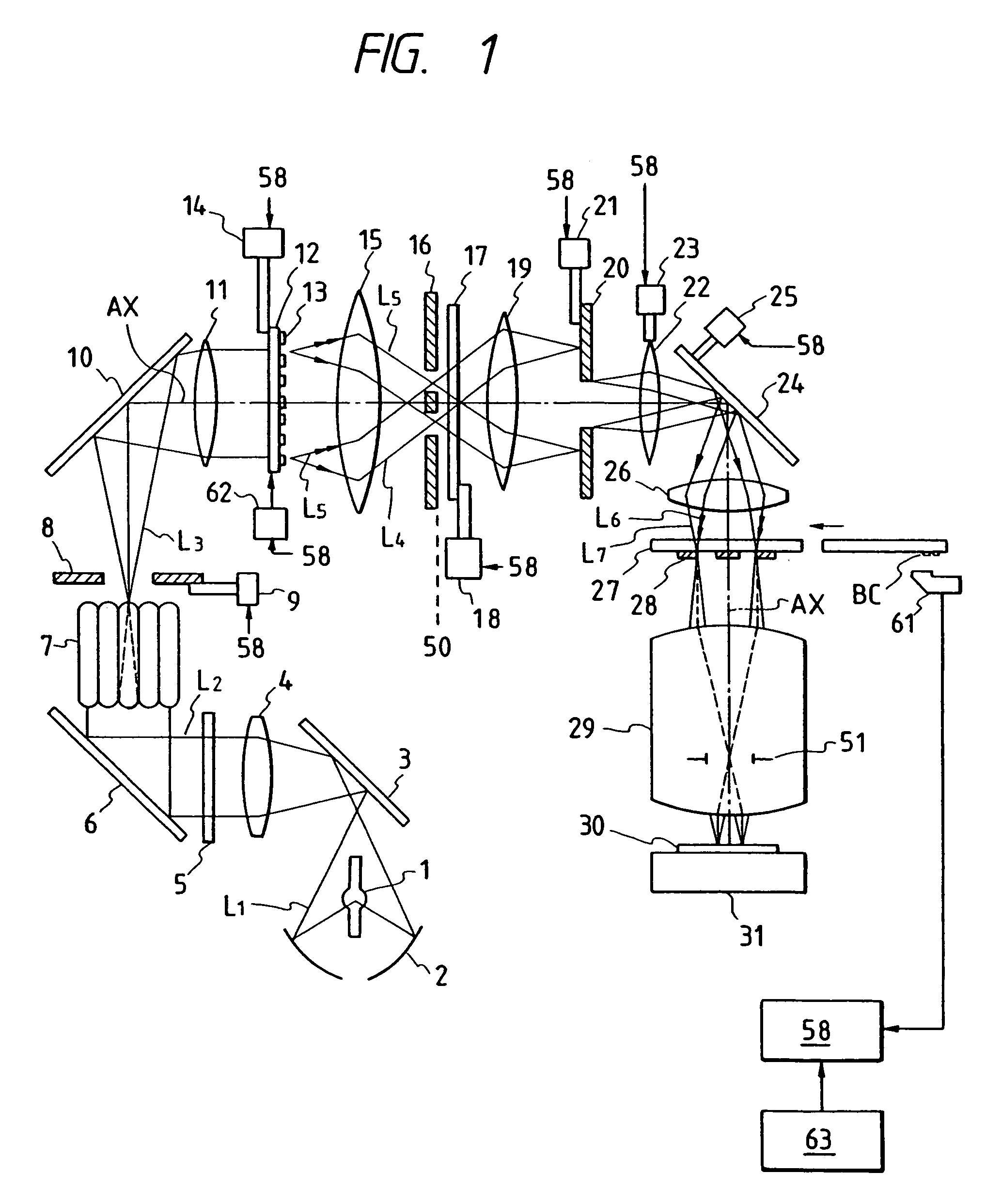
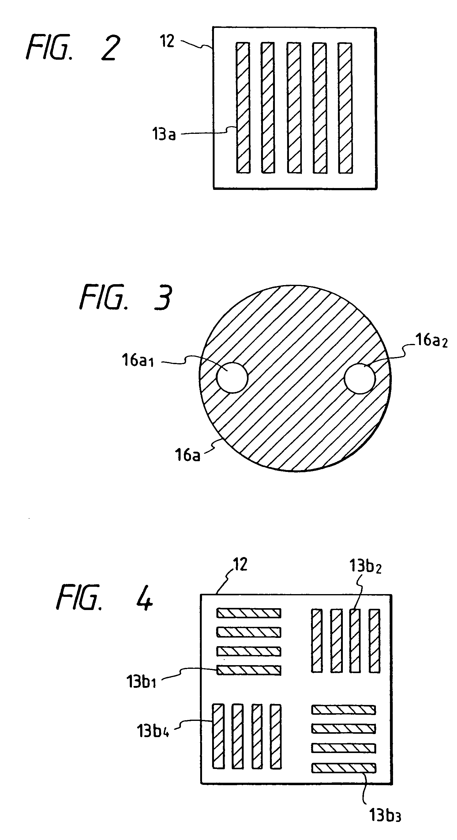
[0121]Embodiments of the present invention will hereinafter be described in detail with reference to the accompanying drawings. FIG. 1 is a block diagram illustrating a whole projection type exposure apparatus in accordance with the present invention. A luminous flux L1 emitted from an exposure light source 1 such a mercury lamp or the like and converged by an elliptical mirror 2 is reflected by a mirror 3. The luminous flux reflected by the mirror 3 passes through a relay lens 4 and is monochromatized by a wavelength selection element 5. A monochromatized luminous flux L2 is refracted by a mirror 6 and is incident on a fly eye lens 7. At this moment, an incident surface of the fly eye lens 7 is provided in a position substantially conjugate to reticle patterns 28. An exit surface of the fly eye lens 7 is formed on a Fourier transform corresponding plane (Fourier transform plane) of the reticle patterns 28 or in the vicinity of this plane. An aperture stop 8 is provided in close pro...

second embodiment

[0222]Next, an exposure method by use of the exposure apparatus in the second embodiment will be described with reference to FIGS. 19A and 19B.

[0223]FIGS. 19A and 19B are flowcharts each showing the exposure method in the embodiment of this invention. A difference between FIGS. 19A and 19B lies in whether the exposure is stopped or not when driving the reflector 54. In advance of the exposure, the shutter 52 is in such a status as to cut off the luminous flux L2. Determined herein are the number of positional changes of the reflector 54, coordinates of the respective positions of the reflector and exposure quantities for the respective coordinates (step 101). As stated before, however, if a so-called light quantity gravity of the illumination light when the luminous flux L5 corresponding to each position of the reflector 54 falls on the reticle 27 deviates from the optical axes AX of the illumination optical system and the projection optical system 29, there exists a possibility of ...

third embodiment

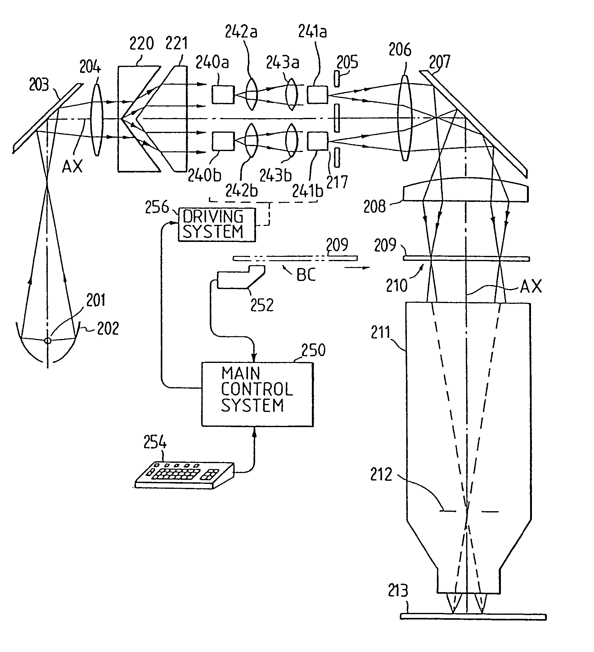
[0264]The individual fly eye lens groups 91A, 91B desirably assume the same configuration and are composed of the same material (refractive index). Respective lens elements of the individual fly eye lens groups 91A, 91B are double-convex lenses as in the Given therein is the example where the light-source-side focal surfaces 91a coincide with the incident surfaces, and the reticle-side focal surface 91b coincide with the exit surface. The fly eye lens elements may not strictly satisfy this relation but may be plano-convex lenses, convexo-plane lenses or plano-concave lenses. Note that the light-source-side focal surfaces 91a of the fly eye lens groups and the reticle-side focal surfaces thereof have, as a matter of course, the Fourier transform relation. Hence, in the example of FIG. 29, the reticle-side focal surfaces 91b of the fly eye lens groups—i.e., the exit surfaces of the fly eye lens groups 91A, 91B—have an image forming (conjugate) relation to the diffraction grating patt...


PUM


Abstract

An exposure apparatus and method to expose an object with an illumination beam irradiated on a mask from a light source disposes an optical unit between the light source and an optical integrator of an illumination optical system to illuminate the mask with an illumination beam, of which an intensity distribution on a Fourier transform plane with respect to a pattern on the mask has an increased intensity portion apart from the optical axis relative to a portion of the intensity distribution on the optical axis.

Description

CROSS-REFERENCE TO RELATED APPLICATIONS[0001]This application is a division of application Ser. No. 10 / 202,007 filed Jul. 25, 2002 now U.S. Pat. No. 6,710,855 (incorporated herein by reference). Application Ser. No. 10 / 202,007 is a continuation-in-part of application Ser. No. 08 / 376,676 filed Jan. 20, 1995, which is a continuation of application Ser. No. 08 / 122,318 filed Sep. 17, 1993, now abandoned, which is a continuation of application Ser. No. 07 / 791,138 filed Nov. 13, 1991, now abandoned. In addition, application Ser. No. 08 / 376,676 is also a continuation-In-Part of application Ser. No. 08 / 257,956 filed Jun. 10, 1994, now U.S. Pat. No. 5,638,211, which is a continuation of application Ser. No. 08 / 101,674 filed Aug. 4, 1993, now abandoned, which is a continuation of application Ser. No. 07 / 847,030 filed Apr. 15, 1992, now abandoned. Application Ser. No. 10 / 202,007 is also a continuation-in-part of application Ser. No. 10 / 124,362 filed Apr. 18, 2002, now U.S. Pat. No. 6,864,959 w...

Claims


Application Information

Patent Timeline
IPC IPC(8): G03B27/42G03B27/54G03F1/00G03F7/20G03F9/00
CPCG03F7/701G03F7/201G03F7/70066G03F7/70075G03F7/70108G03F7/70141G03F7/70158G03F7/70208G03F7/70316G03F7/70333G03F7/70358G03F7/70858G03F7/70883G03F7/70891G03F9/7088
Inventor SHIRAISHI, NAOMASA
Owner NIKON CORP
Why Eureka
Try Eureka