Tri-property rotor assembly of a turbine engine, and method for its preparation

a technology of turbine engines and rotors, which is applied in the direction of wind motors with parallel air flow, wind motors with perpendicular air flow, non-electric welding apparatus, etc., can solve the problems of high loading of turbine disks and blades, creep loading and defect tolerance of the periphery portions of turbine disks and turbine blades, and achieve the effect of flexible manufacturing

Inactive Publication Date: 2005-11-29
GENERAL ELECTRIC CO
View PDF19 Cites 64 Cited by
  • Summary
  • Abstract
  • Description
  • Claims
  • Application Information

AI Technical Summary

Benefits of technology

[0010]The present approach has a great deal of manufacturing flexibility. In the preferred approach, the ring has a first grain size, the central disk hub has a second grain size smaller than the first grain size, and the solid state weld joint has a third grain size smaller than the second grain size. This distribution of grain sizes may be altered, however. The approach is operable where the turbine blades are metallurgically and integrally bonded to the ring, or where the turbine blades are mechanically affixed to the ring but not bonded to the ring, as with a dovetail structure.

Problems solved by technology

The turbine disks and blades are subjected to high loadings during service, and the nature of the performance-limiting consideration varies with radial position.
The performance of the periphery portions of the turbine disks and the turbine blades are limited by creep loading and defect tolerance.
The performance of the hub portions of the turbine disk are limited by tensile and cyclic loading.
These manufacturing techniques, while operable, are difficult to apply in production practice.
The disks are relatively large in size, often several feet across, and it is difficult to achieve a highly controlled microstructure over this large area.
The problem is even more acute when the rotor assembly is a BLISK, where the heat treatment of the disk must be compatible with the bonding process of the blade to the disk.

Method used


Image

  • Tri-property rotor assembly of a turbine engine, and method for its preparation
  • Tri-property rotor assembly of a turbine engine, and method for its preparation
  • Tri-property rotor assembly of a turbine engine, and method for its preparation

Examples


Embodiment Construction

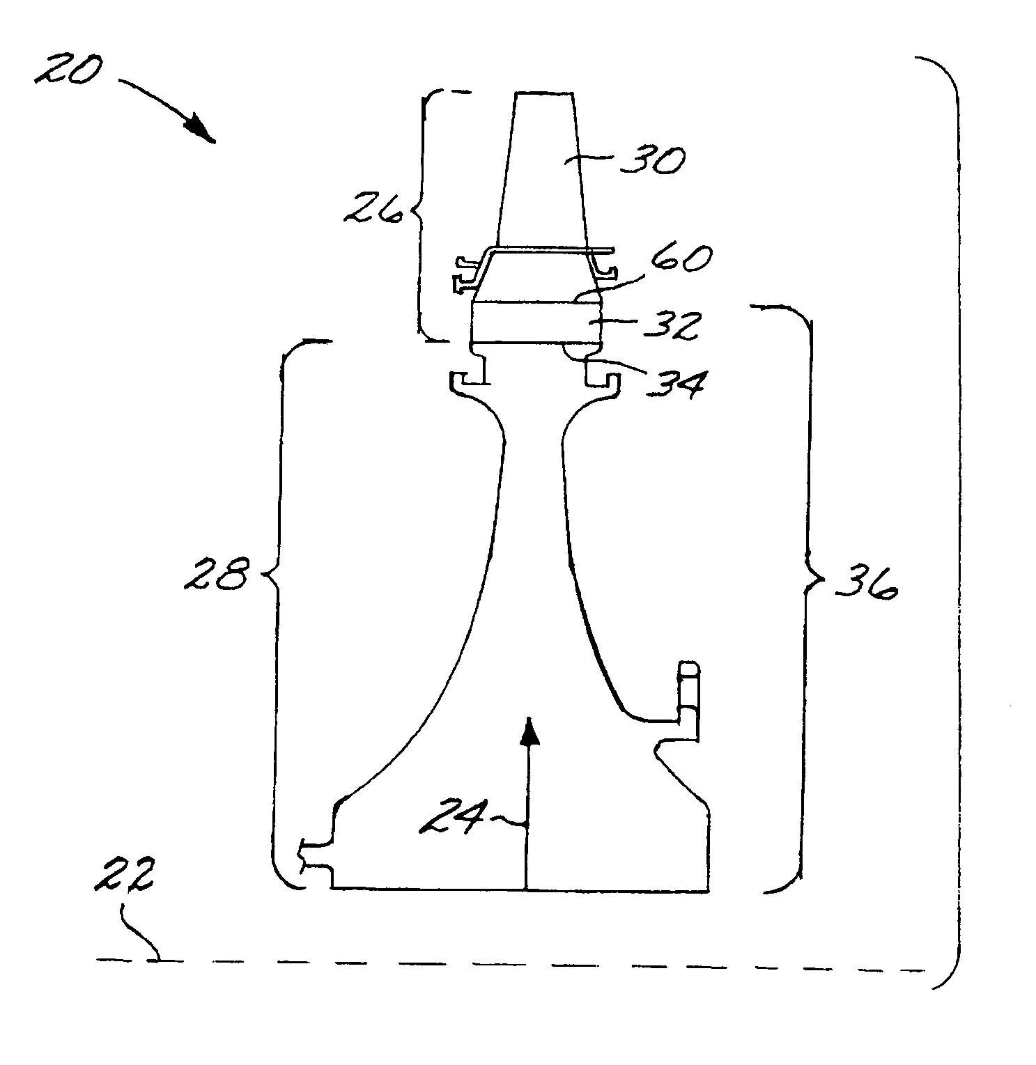
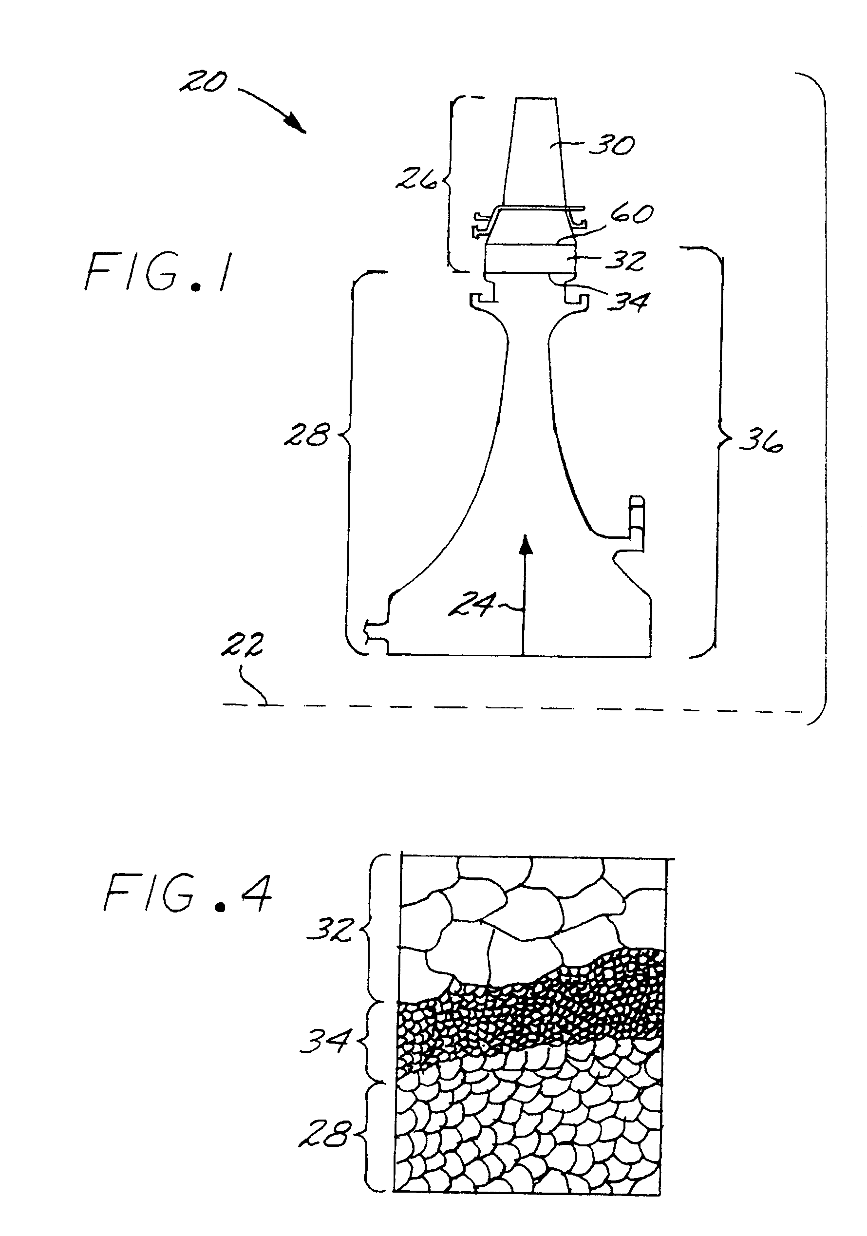
[0020]FIG. 1 depicts, in a partial sectional view, a rotor assembly 20 of an axial flow gas turbine engine. The rotor assembly is preferably a turbine rotor assembly, but it may be a compressor rotor assembly or a bypass-fan rotor assembly. The present approach will be described in relation to the preferred turbine rotor assembly, with the understanding that it may be applied to the other contexts as well. The rotor assembly 20 is axially symmetric about an axis of rotation 22, and a radial direction 24 is defined as perpendicular to the axis of rotation 22.

[0021]The rotor assembly 20 includes a bladed ring 26 and a central disk hub 28. The bladed ring 26 has a plurality of turbine blades 30 (one of which is illustrated) affixed to a ring 32 and extending radially outwardly from an outer surface 60 of the ring 32. The turbine blades 30 are preferably bonded (i.e., metallurgically bonded) to the ring 32, so that the rotor assembly 20 is a BLISK (“bladed disk”). The turbine blades 30 ...


PUM

PropertyMeasurementUnit
grain sizeaaaaaaaaaa

Abstract

A rotor assembly of an axial flow turbine engine has a bladed ring including a ring, and a plurality of turbine blades affixed to the ring and extending radially outwardly from the ring. There is a solid state weld joint between a central disk hub and the ring of the bladed ring. In one approach, the rotor assembly is prepared by bonding the plurality of turbine blades to the coarse-grain ring so that the turbine blades extend outwardly from the ring, providing the fine-grain central disk hub, and solid-state inertia welding the central disk hub and the ring of the bladed ring at a solid state weld joint.

Description

[0001]This invention relates to a rotor assembly used in a turbine engine and its preparation, and, more particularly, to a tri-property BLISK.BACKGROUND OF THE INVENTION[0002]In an aircraft axial-flow gas turbine (jet) engine, air is drawn into the front of the engine, compressed by a shaft-mounted compressor, and mixed with fuel. The mixture is combusted, and the resulting hot combustion gases are passed through a turbine mounted on the same shaft. The flow of gas turns the turbine by contacting an airfoil portion of the turbine blade, which turns the shaft and provides power to the compressor. The hot exhaust gases flow from the back of the engine, driving it and the aircraft forward. There may additionally be a turbofan that drives a bypass flow of air rearwardly to improve the thrust of the engine.[0003]The compressor, the turbine, and the turbofan have a similar construction. They each have a rotor assembly including a rotor disk and a set of blades extending radially outwardl...

Claims


Application Information

Patent Timeline
Patent Type & Authority Patents(United States)
IPC IPC(8): B23P15/00F01D5/02F01D5/28F01D5/34
CPCB23K20/129B23P15/006F01D5/02F01D5/28F01D5/34B23K2201/001Y02T50/673B23K2101/001Y02T50/60
Inventor GROH, JON RAYMONDCARRIER, CHARLES WILLIAM
Owner GENERAL ELECTRIC CO
Why Eureka
Try Eureka