Magnetic proximity interface control

Inactive Publication Date: 2005-11-29
NETWORK APPLIANCE INC
View PDF9 Cites 35 Cited by
  • Summary
  • Abstract
  • Description
  • Claims
  • Application Information

AI Technical Summary

Benefits of technology

[0009]Advantageously, the present invention provides a system and method of connecting components that limits exposure to unsafe voltage

Problems solved by technology

Systems are often redundant in that there are duplicate controllers, duplicate power supplies and duplicate buses interconnecting controllers, drive arrays, and power supplies.
For example, if a power supply failure occurs, the failed power supply may be replaced while the system continues to operate using another functioning power supply or power supplies.
Each opening in the cabinet, such as is required for connectors, presents a potential safety hazard if high voltages are present, and also presents an opportunity for electromagnetic radiation to escape the cabinet.
Fu

Method used


Image

  • Magnetic proximity interface control
  • Magnetic proximity interface control
  • Magnetic proximity interface control

Examples


Embodiment Construction

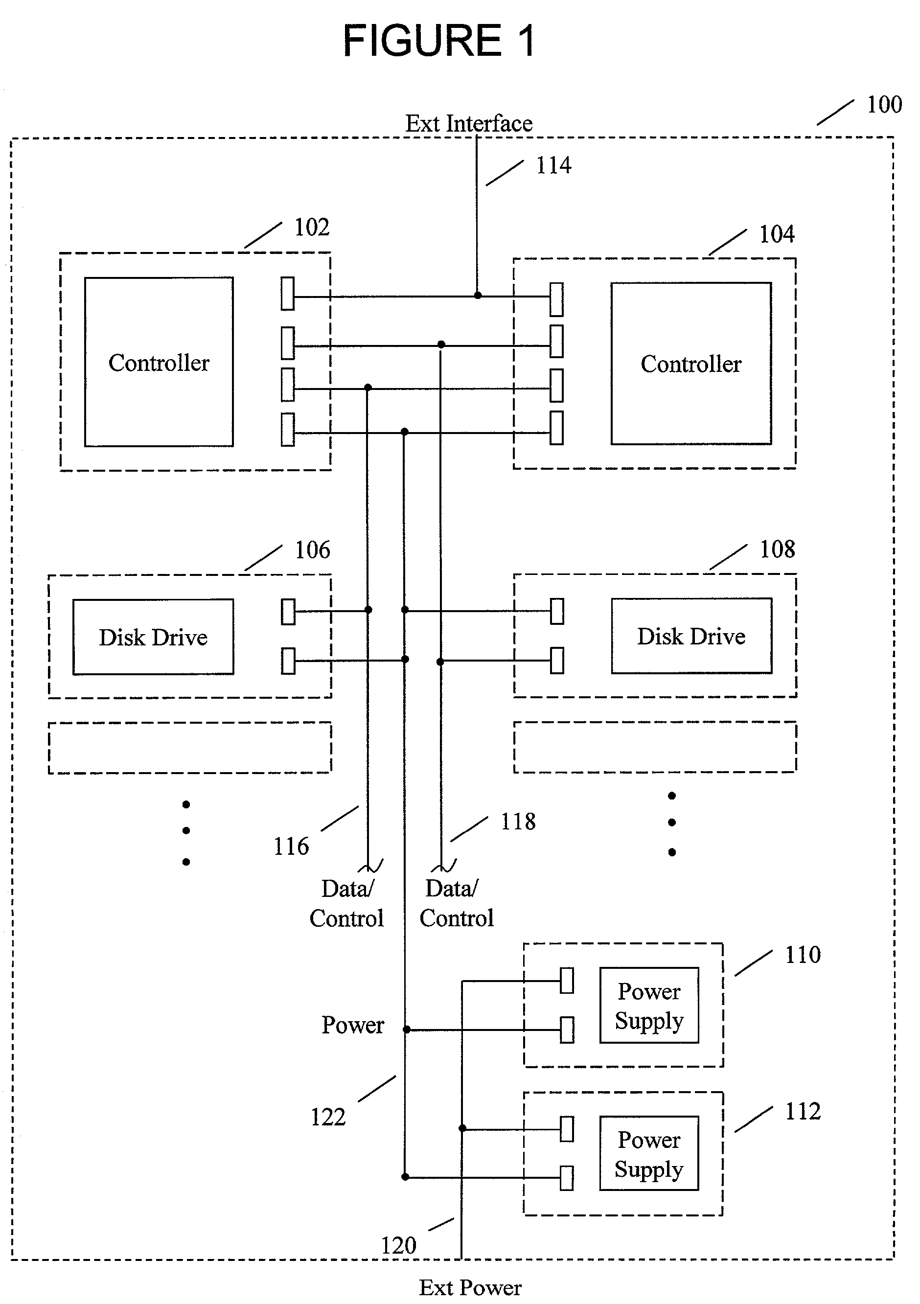
[0017]FIG. 1 is a depiction of a storage system. Storage system 100 comprises controllers 102, 104, disk drive arrays 106, 108, and power supplies 110, 112. Power bus 122 provides power to the controllers and drive arrays. Controller 102 is connected to disk drive array 106 through a first data / control bus 116 and to disk drive array 108 through a second data / control bus 118. Controller 102 communicates data to an external system through external interface 114. This interface may comprise an Ethernet bus, SCSI (Small Computer Systems Interface) bus, fibre channel connection, or other type of interface, either serial or parallel. Similarly, controller 104 is connected to disk drive array 106 through first data / control bus 116 and to disk drive array 108 through second data / control bus 118. Controller 102 also communicates data to an external system through external interface 114. In some implementations, controller 102 and controller 104 may employ separate interfaces (not depicted) ...


PUM


Abstract

Disclosed is a system and method employing a magnetic proximity switch to enable the transfer of power between a power supply unit and a docking unit or to transfer data between a docking unit and a peripheral module such as a disk drive or controller module. Power may be transferred through the switch, or a signal from the switch may be employed to enable a control circuit. The control circuit may control a plurality of voltages or currents and may ramp voltages or currents to limit surge current when a module is installed or removed. The control unit may also be employed to place data and control signals in a high impedance state when a module is not docked, limiting electromagnetic radiation.

Description

BACKGROUND OF THE INVENTION[0001]a. Field of the Invention[0002]The present invention pertains to computer interface control and more specifically to a system and method employing magnetic proximity detection to enable or disable an interface.[0003]b. Description of the Background[0004]Storage systems typically comprise an array of disk drives, disk drive controllers, power supplies and interface cabling. Systems are often redundant in that there are duplicate controllers, duplicate power supplies and duplicate buses interconnecting controllers, drive arrays, and power supplies. Further, systems are often constructed to be readily maintainable and upgradeable. Various components of the system may be replaced while the system continues to operate. For example, if a power supply failure occurs, the failed power supply may be replaced while the system continues to operate using another functioning power supply or power supplies. Similarly, if a controller fails, the system may continue...

Claims


Application Information

Patent Timeline
IPC IPC(8): G06F1/18
CPCG06F1/189
Inventor HANSON, GEORGE E.
Owner NETWORK APPLIANCE INC
Why Eureka
Try Eureka